How to use cal data from MagCal/Magneto into AHRS

My apologise if this a double post, but have not seen my original post show up after approx 8 hours, also will add that the AHRS code l am talking about is MinIMU9AHRS and additional info

Hi everyone, first post and very little knowledge in my head re- coding, so if you could keep your answers as dumbed down as possible for me to follow.
I am trying to better calibrate the magnetometer in the Poloulo MinIMU-9-V3. The project is an Autopilot that Jack Edwards (hi Jack) has designed for a sail boat. I am currently having issue’s which maybe due to that I’m in the southern hemisphere (Tasmania), 71 degree tilt up inclination, where as it seems to be working well in the Northern Hemisphere (61 degree down), but the tilt may not be the final answer.
Using the LSM303 calibration code l have put the min/max into AHRS (painted the IMU inside the sphere analogy given by one of your esteem employees, which is a great practical example of what to do (but l would add that you should paint the outside as well)) and using the PololuAHRS.py software, the headings aren’t linear (0=0,90=110, 180-=180,270=250, approx #, as the North is way off) and there is up to ±10 each way when tilted/rolled manly on Westerly headings ( pitch shows little drift).
To my question , company answer re- calibration, point to Sailboat instrumentation blog for a better calibration, which l have the data from doing the said blog process, but l can’t understand how to implement the matrix and bias into the AHRS code (as the calibration is one of MIN/MAX with no other input available)maybe the ±0.5 in compass tab, line 46?)) can someone point me in the right direction or better still adapt the AHRS code to enable the corrections ?
I have made a crude gimbal to fix the IMU to, which will reduce the tilt error, but if l can calibrate the error all the better, or worst case, a code to alter headings by an error amount to get linear 360. If all this can be answered it will be a great start to the new year.
So best wishes to all at Pololu for the new year, as well as to all the forum members an lookers
Thanks for any answers.
Regards Kevin

The best place to correct the magnetometer readings according to the procedure described in the sailboatinstruments blog, is right after reading the raw values. In the MiniIMU9 AHRS code, this is here:

[code]void LSM303::readMag(void)
{
uint8_t block[6];

if (device == Device::LSM303D)
{
    // LSM303D: XYZ order, little endian
    i2c_mag.readBlock(0x80 | LSM303D_OUT_X_L_M, sizeof(block), block);
    m[0] = (int16_t)(block[0] | block[1] << 8);
    m[1] = (int16_t)(block[2] | block[3] << 8);
    m[2] = (int16_t)(block[4] | block[5] << 8);
}
else if (device == Device::LSM303DLH)
{
    // LSM303DLH: XYZ order, big endian
    i2c_mag.readBlock(0x80 | LSM303DLH_OUT_X_H_M, sizeof(block), block);
    m[0] = (int16_t)(block[1] | block[0] << 8);
    m[1] = (int16_t)(block[3] | block[2] << 8);
    m[2] = (int16_t)(block[5] | block[4] << 8);
}
else
{
    // LSM303DLM, LSM303DLHC: XZY order, big endian (and same addresses)
    i2c_mag.readBlock(0x80 | LSM303DLM_OUT_X_H_M, sizeof(block), block);
    m[0] = (int16_t)(block[1] | block[0] << 8);
    m[1] = (int16_t)(block[5] | block[4] << 8);
    m[2] = (int16_t)(block[3] | block[2] << 8);
}

}[/code]
You would apply the correction matrix and offset vector directly to m[] (as a floating point vector).

It is also essential to set any magnetometer offset and relative scale corrections found elsewhere in the code to zero (offset) or one (scale).

Hi Jim, thanks for the quick response and Happy New Year to you.
I am afraid you haven’t dumbed it down enough.
1)I don’t have the lines of code you show in the MinIMU-9AHRS
After goggling l see you are talking about, minimu9-ahrs/LSM303.cpi, but this is not defined in my AHRS.
could you please show where to find this.
Also you say to "You would apply the correction matrix and offset vector directly to m[] (as a floating point vector)."
Is this
m[0] = (int16_t)(block[0] | block[1] << 8);
m[1] = (int16_t)(block[2] | block[3] << 8);
m[2] = (int 6_t)(block[4] | block[5] << 8);
equal to this
Xc = M11 M12 M13 x Xnc - Bx = m[0] = Xc = m[Xc#]
Yc = M21 M22 M23 x Ync - By = m[1] = yc = m[Yc#]
Zc = M31 M32 M33 x Znc - Bz = m[2] = Zc = m[Zc#]
Mag Cal data = transformation Matrix x Mag non cal - bias =

"It is also essential to set any magnetometer offset and relative scale corrections found elsewhere in the code to zero (offset) or one (scale)."
OFFSET = x,y,z, min/max,= replace min/max with zero
SCALE=???
Thanks for your guidance.
Regards Kevin

The correction as implemented in the Pololu code is not the best, but it should work much better than what you described in your first post. You didn’t describe your procedures well enough to determine what might be wrong. However, the environment where you mounted the sensor might substantially distort the Earth’s magnetic field, in which case the calibration constants are wrong.

I suggest to redo the entire calibration procedure and double check every step.

[quote]1)I don’t have the lines of code you show in the MinIMU-9AHRS[/quote]The AHRS code calls the LSM303 library, which reads the magnetometer. I may have posted code from an older version of the LSM303 library. I just now looked at the Gibhub sources, which is what you should be using. There are some cosmetic differences in how the magnetometer is read.

[quote]Is this
m[0] = (int16_t)(block[0] | block[1] << 8);
m[1] = (int16_t)(block[2] | block[3] << 8);
m[2] = (int 6_t)(block[4] | block[5] << 8);
equal to this
Xc = M11 M12 M13 x Xnc - Bx = m[0] = Xc = m[Xc#]
Yc = M21 M22 M23 x Ync - By = m[1] = yc = m[Yc#]
Zc = M31 M32 M33 x Znc - Bz = m[2] = Zc = m[Zc#]
[/quote]
The first three lines just form three 16 bit integers from the raw magnetometer data (one measurement for each axis). I don’t understand what you mean by the next three.

To introduce the code needed for this correction you will have to modify the libraries in several places. This requires that you have the complete source code, are reasonably familiar with it and that your coding skills are up to the task. Are you familiar with how to write the code for matrix multiplication?

You might consider an alternative AHRS which for theoretical reasons should perform quite a bit better than the MiniIMU-9 AHRS. I described my experience in implementing it in this post: State of the art AHRS for $25

Hi Jim, re- calibration l am doing what pololu describe to get the min/max for the IMU. I am
doing this in the open with no ferrous material around and the compass result is not linear.

[quote=“kevin1961”]Xc = M11 M12 M13 x Xnc - Bx = m[0] = Xc = m[Xc#]
Yc = M21 M22 M23 x Ync - By = m[1] = yc = m[Yc#]
Zc = M31 M32 M33 x Znc - Bz = m[2] = Zc = m[Zc#]
Mag Cal data = transformation Matrix x Mag non cal - bias = [/quote]
This is the transformation matrix from Yury Matseslenak diydrones.com/profiles/blogs/adv … or-dummies

[quote=“Jim Remington”]This requires that you have the complete source code, are reasonably familiar with it and that your coding skills are up to the task.

Familiar with the code, code skills not up to the task, but learning.

Negative, but will do more goggling.
Had read your article and will look closer at the code.
Thanks for now.
Regards Kevin

[quote]Hi Jim, re- calibration l am doing what pololu describe to get the min/max for the IMU. I am
doing this in the open with no ferrous material around and the compass result is not linear.[/quote]
The nonlinearity is disturbing and could indicate a problem with the magnetometer that can’t be solved using the magcal or magneto programs.

Have you made plots of the magnetometer data for a wide variety of orientations, before and after Pololu-style calibration, as described on this page?

sites.google.com/site/waynehold … he-compass

If you don’t get centered circles for XY, XZ and YZ plots (after calibration), post the data and we’ll try to figure out what is wrong.

H Jim, l haven’t done a plot of the data, will look at that next. Have tried the RTIMULiB-Ardunio but can’t even get Magcal to compile. Error below. I have commented out the default mag and uncommented, #define GD20HM303D_6a for the IMUV3

 C:\Users\ff\Desktop\AP\RTIMULib-Arduino-master\RTIMULib-Arduino-master\ArduinoMagCal\ArduinoMagCal.ino:29:0:

C:\Users\ff\Desktop\arduino-1.6.7-windows\arduino-1.6.7\hardware\arduino\avr\libraries\EEPROM/EEPROM.h:43:30: warning: type qualifiers ignored on function return type [-Wignored-qualifiers]

 operator const uint8_t() const       { return **this; }                            ^

C:\Users\ff\Desktop\arduino-1.6.7-windows\arduino-1.6.7\hardware\arduino\avr\libraries\EEPROM/EEPROM.h:92:26: warning: type qualifiers ignored on function return type [-Wignored-qualifiers]

 operator const int() const          { return index; }                          ^

In file included from C:\Users\ff\Desktop\AP\RTIMULib-Arduino-master\RTIMULib-Arduino-master\ArduinoMagCal\ArduinoMagCal.ino:29:0:

C:\Users\ff\Desktop\arduino-1.6.7-windows\arduino-1.6.7\hardware\arduino\avr\libraries\EEPROM/EEPROM.h:145:20: warning: ‘EEPROM’ defined but not used [-Wunused-variable]

static EEPROMClass EEPROM; ^

In file included from C:\Users\ff\Desktop\AP\RTIMULib-Arduino-master\libraries\RTIMULib\RTIMUBNO055.cpp:39:0:

C:\Users\ff\Desktop\AP\RTIMULib-Arduino-master\libraries\RTIMULib\RTIMUBNO055.h: In member function ‘virtual int RTIMUBNO055::IMUType()’:

C:\Users\ff\Desktop\AP\RTIMULib-Arduino-master\libraries\RTIMULib\RTIMUBNO055.h:71:36: error: ‘RTIMU_TYPE_BNO055’ was not declared in this scope

 virtual int IMUType() { return RTIMU_TYPE_BNO055; }                                   ^

C:\Users\ff\Desktop\AP\RTIMULib-Arduino-master\libraries\RTIMULib\RTIMUBNO055.h:71:55: warning: control reaches end of non-void function [-Wreturn-type]

 virtual int IMUType() { return RTIMU_TYPE_BNO055; }                                                     ^

exit status 1
Error compiling.

I would have thought with the complete file it should compile. I did have to install files into the library even thought it says you shouldn’t have to, as it couldn’t find them.
I will add that l have 4x MinIMU9-V3 a fake HMC5883L and all have the non- linearity. That’s what l raised in my first post re, tilt 71 degrees up here in Tasmania

The magnetic inclination in your location is very unlikely to be a problem. It is more likely that you have applied the Pololu-style corrections incorrectly.

Forget RTIMUlib at the moment, and do the magnetometer plots!

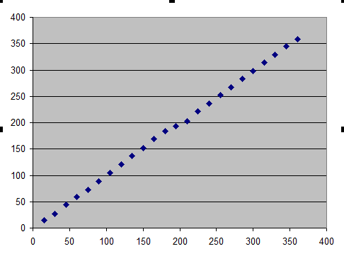
Hi Jim, attached excel2010 sheet showing raw readings with headings taken off a compass rose, approx at the magnetic heading shown. The readings are an average from 500, as you can see it is very squashed.This is done outside with my lap top the closet of any anomalies at about 3M .

Copy of readings Below
Approx mag heading of compass rose
X Y Z
0 54 1 -401 -3793
15 405 -719 -3771.5
30 224 -926 -3759.1
45 -50 -1182 -3701.2
60 -340 -1331 -3669.9
75 -645 -1396 -3642.7
90 -967 -1379 -3614.5
105 -1263 -1288 -3562.3
120 -1518 -1107 -3524.8
135 -1705 -850 -3511.3
150 -1826 -591 -3521.2
165 -1868 -248 -3527.2
180 -1786 37 -3566.5
195 -1620 198 -3625.4
210 -1490 360 -3610.6
225 -1227 676 -3627.3
240 -941 845 -3666.7
255 -606 936 -3700
270 -289 923 -3728.9
285 23 876 -3745.8
300 257 702 -3770
315 450 464 -3788.5
330 555 202 -3789
345 604 -114 3784
360 546 -404 -3766
Regards Kevin
kevin V3 data.xlsx (13.7 KB)

That is a very poorly performing magnetometer. Either it is defective, or the readings are being seriously distorted by the environment.

I looked closely only at the X and Y data. It is possible to correct to some extent for the distortion by using a 2D version of magcal/magneto that I described in this post: forum.sparkfun.com/viewtopic.php?f=42&t=36399

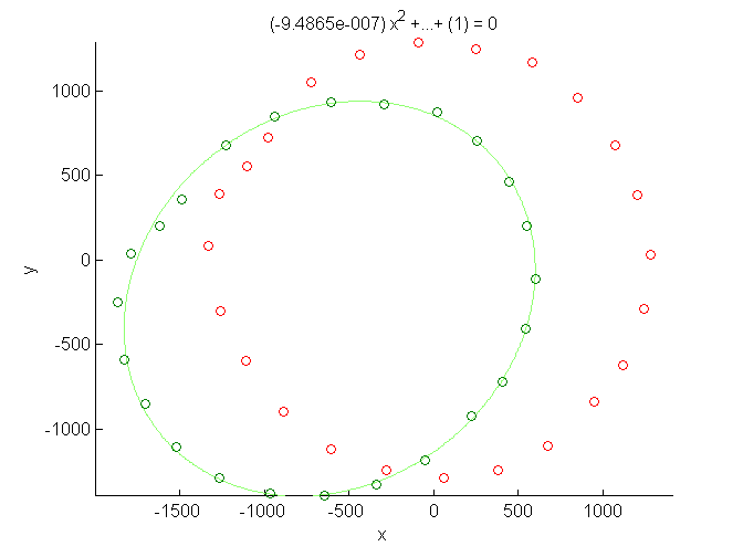
See the corrected and uncorrected data in the plot below (and compare with the before/after plots in the Sparkfun post linked above).

Even after correction the points do not fall on a circle, with large deviations in the upper left hand portion of the plot. I have no idea what could cause that. Note also the off-axis (roughly 45 degree from horizontal) orientation of the uncorrected ellipse which suggests serious hard- or soft-iron distortion in the vicinity of the sensor when the measurements were taken (or malfunction). The Pololu min/max procedure cannot correct for that axial misalignment.

The correction I applied is:

scaled rotation matrix and vector to apply: Q*(XY-XY0)
(1.0630 -0.0819)(X - (-613.8))
(-0.0819 1.1066)
(Y - (-229.5))


I suggest looking at raw magnetometer data taken in several different environments (make lots of plots!) to see what the problem might be.

If nothing comes to mind, to the trash bin with it. They are pretty cheap now, but trust Pololu over an eBay seller.

Hi Jim, as in my previous post, l have 4 x Pololu IMU9 V3 and a 5883L and they are all non linear, they were bought over a month so l imagine they would be from different batches that have been sent to Australia. I will do some more plots of the individual units.
I am taking these measurements out in the open in my front yard. There is a metal fence 10m away and apart from that, only my computer. I built what is around here and know there is nothing else to cause the problem, in the ground or above (there are some blue metal drains in the ground). I have also done this in my back yard with the same results, ironical when tests are done inside my workshop with elect cables and metal everywhere the compass headings are better, but still way off .
I also had played with magnets a few days ago to see if l could place one to improve the compass error, with some good results, but these errors should not be there and would prefer not to have the hassle on my boat.
Has everyone else just calibrate a Pololu IMU9V3 and lived happily ever after. Have people used these in the Southern Hemisphere with big tilt dip UP?
Thanks for your intrest.
Regards Kevin

Hi Jim, would you be so kind as to show how to apply your correction to the AHRS so l could see the difference in the compass headings, compared to using the MIN/MAX method. I have to get some extra connections to enable me to swap over the IMU’s for easier multipul plots. Hope to get some plots posted by tomorrow afternoon.
Thanks
Kevin

I meant to add, the IMU is silk screen up, taped to a piece of wood, which is screwed to a larger piece of wood, with stainless screws, the compass rose system is a part sheet of ply with the rose drawn on it, fixed to a plastic drum with stainless screws. I have about 8M of 4 core flat cable connecting the IMU to the Mega. I have found 4 core screened cable won’t work for the connection at anything longer than 1.5M, it locks up the Mega, unscreened flat all OK.
No heading interference when l even wrap the cable around the IMU, so don’t believe screened cable makes a difference, apart from making things worse.
Regards
Kevin
I have now seen the EDIT option!!!, will use next time.
In your Calibration and shifting the sort of a circle to the centre, what difference does it make to the compass heading?
What difference to the compass heading does the circle that isn’t a circle make, is this were the non linearity comes from, or from the circle not being centred, or a combination of both?

Hi, Kevin:

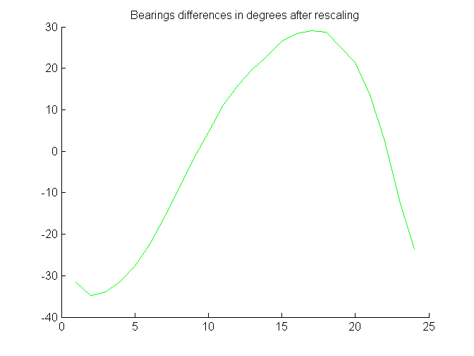
Below is a plot showing the difference in headings made by the applied correction. As you can see, the uncorrected headings are off by +/- 30 degrees.


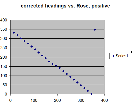
I applied the corrections to your original data and pasted them into your Excel spreadsheet (attached), and am now more confident in the magnetometer performance. The corrected headings are quite linear with respect to the compass rose, but an additional offset and change of sign is necessary. (The sign problem may be due to my misunderstanding of the Excel atan2 function). That is not a problem.

So, the positive magnetic inclination in Tasmania (absolutely lovely island, BTW) is not a problem either. In any case, the 3D correction calculated by magcal/magneto is much preferred!


I am not very interested in rewriting the AHRS code, as it will perform less well than the RTIMUlib, as that uses a full blown Kalman filter and quaternion maths. I suspect it would be a lot easier to implement the correction in RTIMUlib. But if you want to continue with MiniIMU AHRS, perhaps one of the Pololu engineers would be willing to help.kevin V3 data.xlsx (18.3 KB)

PS: The long cable is potentially a serious problem for I2C communications and you can expect intermittent errors at best. I2C is really intended for inter-chip communications on circuit boards.

It would be best to have a separate processor close to the IMU to calculate the orientation, and transmit that to a steering processor via the serial port.

Matlab code used to calculate and perform correction of magnetometer data:

% File: magcal_2d.m
% This MATLAB program calculates the calibration parameters for a 2D magnetometer.
% As is customary, data for one or two complete revolutions of the magnetometer
% should be collected while held level, points closely spaced if possible.
%
% uses published Matlab function EllipseDirectFit.m
% http://www.mathworks.com/matlabcentral/fileexchange/22684-ellipse-fit-direct-method
%
% First step: collect data and produce a CSV file (comma separated values) of
% magnetometer X and Y values (can be raw).
%
% Second step: from Matlab File Menu, import CSV file of (max, magy)
% measurements into array kevin_V3_data.
%
% Third step: execute magcal_2d.m
%
% This work was inspired by the 3D procedure described in:
% http://sailboatinstruments.blogspot.com/2011/08/improved-magnetometer-calibration.html
%

A = EllipseDirectFit(kevin_V3_data);

% modified coefficients of equation for ellipse
% from http://mathworld.wolfram.com/Ellipse.html

a = A(1);
b = A(2)/2;
c = A(3);
d = A(4)/2;
f = A(5)/2;
g = A(6);

% X0, Y0 offset (centroid of ellipse)

x0 = (c*d - b*f)/(b^2 - a*c);
y0 = (a*f - b*d)/(b^2 - a*c);

% semimajor and semiminor axes

numer = 2*(a*f*f+c*d*d+g*b*b-2*b*d*f-a*c*g);
denom1 = (b*b-a*c)*( sqrt((a-c)^2 + 4*b*b) - (a+c));
denom2 = (b*b-a*c)*(-sqrt((a-c)^2 + 4*b*b) - (a+c));
a_axis = sqrt(numer/denom1);
b_axis = sqrt(numer/denom2);

% angle of ellipse semimajor axis wrt X-axis

if (a < c) theta =        0.5*acotd((a-c)/(2*b));
else       theta = 90.0 + 0.5*acotd((a-c)/(2*b));
end

s=sprintf('x0 = %5.2f y0 = %5.2f a = %5.2f, b= %5.2f, theta(d) = %4.1f', ...
         x0,y0,a_axis,b_axis, theta);
disp(s);

% rotation matrix to align semimajor axis to X-axis

ct=cosd(theta);
st=sind(theta);
R = [ct st; -st ct];
xy0 = [x0 y0];

%rescale vector, correct for difference in magnetometer X & Y gains

scale = [b_axis/a_axis,1];

% final result: matrix to align ellipse axes wrt coordinates system, normalize X and Y gains and rotate back.

Q = R^-1*([scale(1) 0; 0, scale(2)]*R);

% correct the input data

for i = 1 :  length(kevin_V3_data)
xy(i,:) = ( Q*(kevin_V3_data(i,:)-xy0)' )';
end

csvwrite('corrected_data.csv',xy); % write out corrected data

% replot scaled data. Set "hold on" in EllipseDirectFit.m

A = EllipseDirectFit(xy);

% residual plot

figure;

p1 = (180./3.14159).*atan2(kevin_V3_data(:,2),kevin_V3_data(:,1));
p2 = (180./3.14159).*atan2(xy(:,2),xy(:,1));
xp = 1:length(kevin_V3_data);
hold on
title('Bearings differences in degrees after rescaling');
for i=1:length(p1)
    pd(i) = p1(i)-p2(i);
    if (pd(i)>180)
        pd(i) = pd(i)-360;
    end
    if (pd(i) < -180)
        pd(i) = pd(i)+360;
    end
end
plot(xp,pd,'-g');

disp(' ');
disp('scaled rotation matrix and vector to apply: Q*(XY-XY0)');
s = sprintf('(%6.4f %6.4f)*(X - (%5.1f))',Q(1,1),Q(1,2),x0);
disp(s);
s = sprintf('(%6.4f %6.4f)*(Y - (%5.1f))',Q(2,1),Q(2,2),y0);
disp(s);

Hi Jim, thanks for your efforts. Any guesses why all the IMU’s are so far off?
It is way past my current ability to alter the RTIMUlib (Currently I can’t even get it to compile the MagCal code),
if you are up to that it would be appreciated, as l could then incorporate it into Jack Edwards Auto Pilot code.
In my readings l have come across were it has been said that the process power required to use the Kalman filter/quaternion maths is a concern, (RTIMUlib, now l understand why it is better), but that DCM is up to the task, but much easier on process power.

Maybe the RTIMUlib is too much for the Ardunios, or will a Mega run it. Re- Comm’s, I can mount a separate Mega if it was required close to the IMU, but the current method does work elsewhere.
There is still some additional PID maths to do with the Mega for heading error, so l suppose it is a suck and see approach.
Hello Pololu (Happy New year), are you able to help in altering the AHRS to enable a better means of calibration, that would be the icing on the cake.
Thanks Jim for your efforts, I see the rescaled “theta’ pos” is very much a 15 degree step, just the headings are going backwards? l can correct the 15 degree off with the Magnetic variation correction but maybe not the reverse rotation, but l imagine there is a way around that.
Regards
Kevin

Kevin:

RTIMUlib runs just fine on an Arduino, much, much faster than you need for a boat autopilot. A Mega won’t help. My version ran on a Pro Mini. Judging from the error messages, you are missing the EEPROM library, and some constant is not defined correctly, because it is looking for the BNO055 (see below).

To make the “corrected” compass headings from my simple minded approach agree with the compass rose, just change the sign and add an appropriate constant. Look up “least squares line fit” if you want to calculate the best possible correction. Here is one online calculator, but Excel can do that too: neoprogrammics.com/linear_le … egression/ Using the latter, the constant is 346.


If you are really not up to the task of modifying code, I strongly recommend the BNO055 for a complete, out of the box and inexpensive 9 axis orientation solution. It is accurate to 1-2 degrees absolute and has a built in calibration procedure for all three sensors. learn.adafruit.com/adafruit-bno … r/overview

In fact, this summer I built an autonomous motor boat that could navigate between arbitrary GPS waypoints, with the BNO055 as the primary orientation sensor. Course error was never more than 2-3 meters at the waypoints. Of course, I used a Pololu Orangutan to read the GPS, the BNO055, do the navigation and control the motors! This was in preparation for a future sailboat entry in the Microtransat challenge.

Cheers, Jim

Hi Jim, thanks for your help, my GURU Jack, will be digesting all this, as it is his baby and will, lm sure nut it out.Still hoping Pololu are able to update there code to enable better calibration, HELLO Pololu (particle when they tell people there is a better method).
As you are suggesting Jim, we have been thinking of trying some other IMU so please Pololu if you can rectify this, it would save some bad press, as we are well aware now of possible (l am being nice) better performing IMU’s.
Regards Kevin
PS. My programming skills aren’t currently up to advanced maths programming, but lm researching and interested to improve. Also have read lots of your posts,l have found you to be up with all this and willing to help and pass on some of your knowledge, so thank you Jim

Hi, Kevin:

Don’t be discouraged! Pololu doesn’t make the sensors, only the breakout boards, and I believe that the ones they use perform as well as any currently on the consumer-grade market.

ALL magnetometers need to be frequently recalibrated and corrected and with correction, yours is accurate to within about 3 degrees (possibly better).

It is not a good idea to draw conclusions from just one experiment, but the uncorrected response from yours is worse than I’ve seen before. The sensor may not be to blame, as environmental effects can easily cause this. I suggest to experiment with the “naked” sensor on a short (~20 cm) cable to eliminate some of them. Again, do lots of plots.

Finally, I don’t feel comfortable being responsible for altering and/or maintaining software that will be used on navigation equipment with which I’m not familiar and cannot access. Too many things can go wrong.

You have a great project, so stick with it!

Jim

Edit: I looked closer at the error messages from your attempt to compile RTIMULib, and I was wrong about the EEPROM library in a previous post. You do have the EEPROM lib, but it may not be compatible with your version of the Arduino IDE [quote](C:\Users\ff\Desktop\arduino-1.6.7-windows\arduino-1.6.7\hardware\arduino\avr\libraries\EEPROM/EEPROM.h:43:30: warning: type qualifiers ignored on function return type [-Wignored-qualifiers].[/quote] I used Arduino IDE version 1.0.5-r2 to successfully compile and run the RTIMULib programs, so download and try that version, after double-checking all the #define statements.

Hi Jim, you have given me some encouragement, l understand the chips aren’t there’s. But would the BNO055 just work you think (on board cal is most probable the big advantage), or is it most likely an environment issuing, l still wonder about the whole Southern Hemisphere thing.
I have only recently increased the length of the cable , as mentioned about mega lock up, even with a short cable <1M still had the same issues and testing inside and out.
Guru Jack and l are slowly going thru some of the issues,it’s all his work, l am just a test dummy down in the Southern Hemisphere causing him grief.
Thanks again, will try a different version of IDE re- RTIMULib., but does that enable me to correct my Mag issue, or am l back to square 1.
Have looked at the “least squares line fit” but more research to do, starting looking at some of the formulas, like theta and radians, but my head hurt some much l had to quench it with coups amount of home brew beer, then it really got confusing, its all a learning curve.
I must admit l previously thought people were pretty nerdy to be playing with remote control type stuff, but if you are designing and building things, l never realised how intelligent you need to be to work this advanced maths stuff and l take my hat off to you designer/builders, not of course to people who buy a remote car/boat and drive it around, my thoughts of them haven’t changed.
Regards
Kevin