I installed a PSU Molex the wrong way around and fried an ATMega with 12V instead of 5V, and its possible that the four A4988 on the same board are toast as well. I’m hoping that since they weren’t driving the motors at the time, they might have survived, so would like to check them if possible.
I’m on OSX, so the Windows tool doesn’t help me, nor do I have an oscilloscope. Is there anything I could measure with a multimeter which could tell me what’s what?
Using them with a Gen7 1.2 RepRap board loaded with Teacup firmware and Pronsole & ReplicatorG on the computer.
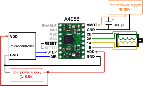
To test one of your A4988 boards, you can just hook it up with some minimal connections and then measure the voltages on the motor outputs. You can use this diagram as a starting point, though you can just tie STEP and DIR to ground and leave the motor disconnected. (Be sure not to connect or disconnect the motor while the driver is powered!)
If you want to be even more sure, you can then try connecting the motor and manually stepping it by driving STEP high a few times.
The pot setting isn’t relevant for the first test because you won’t have a stepper motor connected (there won’t be any current to limit). I would leave the pot where it is or put it somewhere in the middle of its range.
If you want to connect a stepper motor and manually step it, you can connect your STEP input to VDD through a pull-up resistor (maybe 1k to 10k) and then tap the pin with a grounded wire. Or you can use a pull-down resistor on the pin and tap it with a wire connected to VDD. The point is to generate some rising edges on the pin, which will cause the unit to step the outputs. Note that the current limit is relevant for this test, so you should adjust it to an appropriate value with the STEP input held fixed at ground or VDD before you start trying to step it. If you have it too high, you could burn out your stepper motor or overheat your driver (thermal protection should keep the driver from being damaged, but it will make it seem like things aren’t working right), and if you have it too low, the stepper motor might not have enough torque to move.
I just got around to trying out the first suggestion, and as per pololu.com/picture/0J3360.60 … d95a326a5b I hooked up 5V to VDD, and ground to GND, STEP and DIR. I measured the current between 2A/2B and 1A/1B respectively, but registered nothing there, regardless of how the pot was set.
Do I understand you correctly that this would confirm a busted driver?
Reading the manual stepping instructions, I’m still not getting the picture. 5V to VDD, and VDD to STEP via a 100k ΩR. I’m assuming that GND and DIR are connected to ground, but which connection am I supposed to close to get the motor to step? Quickly apply current at VDD? And would I have to supply power through VMOT to get movement, or isn’t that required if there’s no load on the motors?
The first suggestion was to try making connections without a stepper motor connected, in which case no current will flow from the outputs; in this case, you should be measuring the stepper motor output voltages, not current. Did you have a stepper motor connected when you tried to measure the current?
I don’t really understand what you’re asking or how you would “quickly apply current at VDD”. If you want to manually step the stepper motor, you need to make at least the minimal connections described in the diagram on the product page, except instead of connecting STEP and DIR to a microcontroller, you would connect them to VDD through a pull-up resistor (1 to 10k if possible, but 100k should still work). You can then manually step the motor by tapping the STEP pin with wire that is connected directly to ground. Every tap should step the motor at least once (maybe more if there is some physical bouncing involved in the tap).
My mistake. In the first instance I measured voltage without a motor connected, over 2A/2B and 1A/1B, and nothing registered.
I didn’t apply voltage to VMOT/GND though; Will I still registers something over 2A/2B and 1A/1B?
This is what I was after in the previous post, thanks. The same question applies here though, if I hook up a motor, won’t I have to add power on VMOT/GND to get it to move?
Yes, in both cases you need to be supplying the motor voltage, VMOT, to get a meaningful result. Note that the VMOT connections are part of the minimal connection diagram we’ve been discussing; it is important you make all of those connections except for the ones I’ve explicitly mentioned you need to change.
Ok, got it. I hadn’t thought of the other connections in the linked schematic and only focussed on the connections in your comments. Thanks for the patience. Here’s what I tried now. nth time is the charm.
5V hooked up to VDD
Ground to GND/DIR/STEP
SLEEP connected to RESET (tried both with and without this)
4.5V to VMOT (motors rated 4V) but also tried 12V
Pot from mini to maxi.
With the above combinations, motors not connected, I measured the voltage at 2A/2B and 1A/1B but got nothing.
Connected VDD to a 10k resisistor, which in turn is connected to STEP/DIR. All else is similar as above (tried SLEEP/RESET jumper on and off, 4.5V as well as 12V for VMOT, max/min pot) but did not connect motors. Instead tapped and also held ground to STEP and measured voltage at 2A/2B and 1A/1B, registering nothing.
Is there still something I’m missing, or could this be conclusive? Cheers.
From the diagram and product description, you can see that VMOT needs to be 8 V or higher, so let’s stick with the case where you are using 12 V. Are you making sure to connect your motor supply ground to the stepper motor driver and your logic supply ground to the stepper motor driver? What is your logic voltage source?
Can you try measuring your stepper motor outputs again (with STEP and DIR held high and RESET tied to SLEEP)? If you still don’t see anything, can you use your multimeter to measure the voltage between the driver’s VMOT pin and GND and the driver’s VDD pin and GND? Do you see the voltages you expect on these pins?
Hello. I have the same problem though I am in a dilemma whether my a4988 driver is not working or my motor is out of order. I checked the motor output voltages and they are showing minimal voltages like 50 mV. So my question is how much voltage should I expect from the output pins.?
The original poster said he supplied a higher voltage to VDD than the drivers are rated for. Did you do the same thing? Has your driver ever worked? Can you post pictures that show how everything in your system is connected? What kind of power supply are you using? Can you post a link to a datasheet or product page for your motor? There is no set output voltage for the output pins; the voltage will depend on many things in your system. However, 50mV seems pretty low.
Thanks for the reply nathan.
So initially I bought 4 a4988 drivers and I hooked them up according to the minimal wiring diagram. And they were working fine. But then I guess two of them got fried because of increases resistance on the motor(Is this possible?). The other two i checked were still working.
I then transported my setup to a different lab which is some 500 m apart from initial position. During transportation the motors suffered some mechanical vibration as the road was patchy.
Then in the new lab I again setup the minimal wiring circuit with one of the two working drivers. And it stopped working…
I checked with the other one as well but with same result. I checked my Stepper motor by putting an Led on one of the coil. And it was glowing as I rotated the shaft manually. [But is that a sufficient condition to know for sure that the motor is good to go?]
For VDD I used arduino’s 5v powered by my PC. I used a 12v power supply for the driver with 1000 micro farad capacitor in parallel.
Can you post pictures that show how you have everything connected? What did you set Vref to on the drivers? In general, stepper motors are difficult to break, so it seems unlikely your motors are the issue.
As I mentioned earlier in the thread, there is no set output voltage for the output pins. Those could be valid values. If you want to troubleshoot your system, could you please post pictures that show the motor drivers and all of the connections in your system (including any soldered connections you made)? What did you set VREF to? If you did not set the current limit for the drivers using VREF, you can find instructions on how to do so in the video in the Setting the Current Limit on Pololu Stepper Motor Driver Carriers post on our blog. Have these stepper drivers ever worked in your system? If so, what happened before they stopped working?
I have been reading the posts and as I have a similar problem I am interested in and thankful for the replies and comments, Looking at these it seems that the test procedure should follow the following sequence,
disconnect the motors
connect pin 7 (STEP) and pin 8 (DIR) to pin 9 (GND)
connect a voltage to pin 10 (VDD) of 3 - 5.5v
ensure pin 9 is connected to Ground
5 test for voltage between pins 11 and 12 (1A-1B)
6 test for voltage between pins 13 and 14 ( 2A-2B)
Using the pin designations for a 16 pin Integrated circuit chip.
As 1A and 1B are opposing ends of the same coil one end will be output the other an input
likewise for 2A and 2B. am I correct
The board will not function correctly if VMOT is not connected to a power source and, in general, testing the output pins for voltage only makes sense in some situations. If you are having problems with one of our carrier boards, please post pictures of all of your connections (including any soldered connections you made) and describe how it is behaving, we should be able to help you troubleshoot the problem.
Hi nathanb, apologies for the delay in getting back to you.
I suspected that vmot and gnd, pins 15 and 16 were the power connections
for the motor. but I am not really sure how to connect in into a practical
circuit.
the real problem for me is how to test the controllers using a bench power
supply and a solderless breadboard.
I have a sintron prusa i3 3D printer which uses an Arduino ramps 1.4
controller combination. The background to my problem is that having had all
of the problems that are well documented regarding this printer. I got to a
stage where I had overcome them and then the one thing left went wrong when
a loud popping sound akin to the sound of a capacitor exploding occurred
somewhere on the controller set-up.
After testing the arduino board. it seemed ok some testing of the ramps
board revealed nothing so I wanted to test the motor controllers and was
looking for a way to do this.
There are links earlier in this thread to a minimum wiring diagram for our A4988 driver boards. It does not look like the printer you mentioned comes with A4988 carrier boards we manufactured. You might try contacting your boards’ manufacturer for additional support. If you think you have boards we manufactured, please post pictures of them here.
