How can I understand if my MC33926 burnt?

Hi dear Pololu staff,

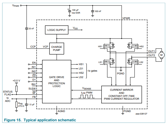
I am using MC33926 DC Motor Driver. So I want to ask a few questions, which might be basic but I’d appreciate it if you would explain it as if I am a dummy.

  1. The Paths
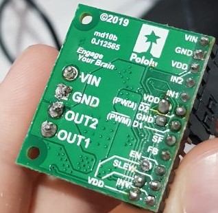
    How can I understand if I soldered onto a path? Actually, are those paths conducts electricity? Since they are painted green, I thought not.
    photo5936005713925092428

  2. Default-Overriding Jumpers
    At first, I didn’t understand the logic and soldered them with headers. After that, I read a forum post that tells the poster to short circuit them. So why should I short circuit them? Can’t I leave them unconnected?

  3. How can I understand if my motor driver is burnt?
    I can’t drive my motor so I thought the motor driver might be burnt but I don’t know how to troubleshoot properly. So my setup is this;
    My motor is a 12V 5A DC motor without an encoder which is not a Pololu.
    My adapter is 12V 5A.
    I am using Arduino with digital pin 3 for PWM and pin 8, pin 9 for IN1, IN2 respectively. No other connections except power supplies and grounds. I am not using any capacitor too, like there is no circuit other than these boards. I am not in great shape electrical knowledge-wise.

This is the Arduino code that I used;

const int pwm = 3 ; //initializing pin 2 as pwm
const int in_1 = 8 ;
const int in_2 = 9 ;
//For providing logic to L298 IC to choose the direction of the DC motor
void setup() {
pinMode(pwm,OUTPUT) ; //we have to set PWM pin as output
pinMode(in_1,OUTPUT) ; //Logic pins are also set as output
pinMode(in_2,OUTPUT) ;
}
void loop() {
//For Clock wise motion , in_1 = High , in_2 = Low
digitalWrite(in_1,HIGH) ;
digitalWrite(in_2,LOW) ;
analogWrite(pwm,255) ;
/* setting pwm of the motor to 255 we can change the speed of rotation
by changing pwm input but we are only using arduino so we are using highest
value to driver the motor */
//Clockwise for 3 secs
delay(1000) ;
//For brake
digitalWrite(in_1,HIGH) ;
digitalWrite(in_2,HIGH) ;
delay(1000) ;
//For Anti Clock-wise motion - IN_1 = LOW , IN_2 = HIGH
digitalWrite(in_1,LOW) ;
digitalWrite(in_2,HIGH) ;
delay(1000) ;
//For brake
digitalWrite(in_1,HIGH) ;
digitalWrite(in_2,HIGH) ;
delay(1000) ;
}

I am using Arduino for just testing, normally I will be using Raspberry Pi 4.

I am really sorry if I made a mistake or transgressed forum rules.

With kind regards,

Sami

Hello.

The traces on the board are covered by a mask, which is possible to scratch off, but a problem like you are concerned about is very unlikely at this point. Unless you are overriding the default state of the board, it will be in a disabled state. You do not need to use the default-override jumpers to do this (e.g. you could drive them from your microcontroller), but using those pins reduces the number of required connections.

The default overriding jumpers on the board are available for pins D1, D2, EN, SLEW, and INV.

By default, D1 and D2 will disable the motor output, so you will need to do something with both of them to enable it. You should be connecting your PWM input to one of those pins (usually D2), and you can connect the other one to the neighboring default-override pin. It is okay to solder headers to those pins and use a shorting block to make that connection.

The default behavior of the EN pin is to put the board in a low-current sleep mode, so you will either need to drive that pin HIGH with your microcontroller, or connect it to its neighboring default-override pin.

SLEW and INV are optional; in general, the SLEW pin’s default behavior only needs to be overridden if you are using a PWM frequency faster than 10 kHz and the INV pin can be used to swap the meanings of IN1 and IN2.

Aside from those pins, there are a couple of other things that are potentially concerning in your post.

The soldering, particularly on the terminal blocks (VIN, GND, OUT1, and OUT2), look like they are not making good contact with the pads on the board. Adafruit’s Guide to Excellent Soldering is a good reference for what a proper solder joint should look like. I recommend reworking those pins until they are properly wetted to the pads.

Also, you mentioned your motor is “12V, 5A”. Can you clarify if that 5A rating is a stall current, operating current, or some other kind of rating (such as max efficiency)? Do you know what the stall current of your motor is at 12V? The MC33926 can only handle around 3A continuously with a 5A peak. Please note that starting up at full speed from a stop can cause your motor to draw upward of it’s stall current, and switching directions at full speed can briefly draw upwards of twice the stall current, so even if that 5A rating is the stall current, you should probably be taking some measures to reduce sudden bursts of current, such as acceleration limiting.

Brandon

1 Like

Thank you, Brandon.

Yes, indeed 5A is the stall current. The motor provides 10Nm stall torque and 6Nm was enough for me. So I thought I would drive it with 3A continuously.
Ah, my bad. Even though I knew when I bought the driver, I forgot that MC33926 provides 3A continuously. But I tried with the lines;

analogWrite(pwm,150);
analogWrite(pwm,140);
analogWrite(pwm,1);

and still didn’t work. How can I limit the acceleration, reduce the sudden burst of current?
Maybe a capacitor?

Hello.

I would expect the MC33926 to still be able to drive the motor without acceleration limiting; it is just a precaution to avoid situations where the motor could draw large bursts of current. Have you changed your setup to override the default behaviors of the EN pin as well as whichever D# pin you are not using for PWM?

There are many ways to add ramping to your code, for example you could use a simple FOR loop like this:

for(int i =0; i<150; i++){
    analogWrite(pwm,i);
    delay(3);	#adjust this delay to control how quickly it ramps up
}

Also, do you have a load on the motor? If you do, I recommend removing it for now. A general recommendation for continuous operation of brushed DC motors is to operate them at around 25% of their stall torque (and therefore stall current) at most. So if you need to run your 5A stall motor at 3A continuously to get the torque you need, the motor is probably underpowered for your application. Operating it like that could drastically reduce its lifetime.

If you are still having problems getting the motor to run, can you post pictures of your setup that show all of your connections as well as your complete updated code?

Brandon

1 Like

Brandon. Thank you, it worked!

I didn’t understand the EN and D# pin at your first comment, sorry for that. I did as you’ve said and it worked. And thank you for that valuable information.
Thank you very much, really. I appreciate it.

So one last question then, I hope. Vpwr in this diagram is Vin in our case, right? What is CCP? I mean I assume the motor driver is the inside of the jagged lines. I will use these capacitors as;
Vin-(Vin pin+(capacitor-GND))
-: electrical connection
Is this true?

image

Hello.

The dashed line in that diagram from the datasheet represents the driver IC (which does not include our carrier board). Our board does not break out the CCP pin. The 33nF cap is included on our board from CCP to VIN. You can see this in the schematic diagram at the bottom of the MC33926 Motor Driver Carrier product page.

Brandon

1 Like

Thank you