Hi, I’m currently using the High-Power Stepper Motor Driver 36v4 for a project that involves an Arduino Uno to move a 1.7 A stepper motor. However, when I run the example code "BasicSteppingSPI, the motor does not run or seem to receive any power at all.
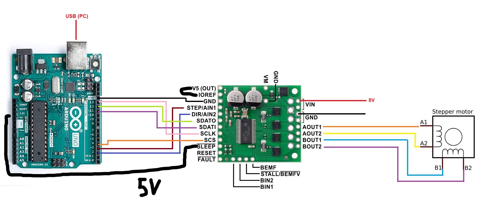
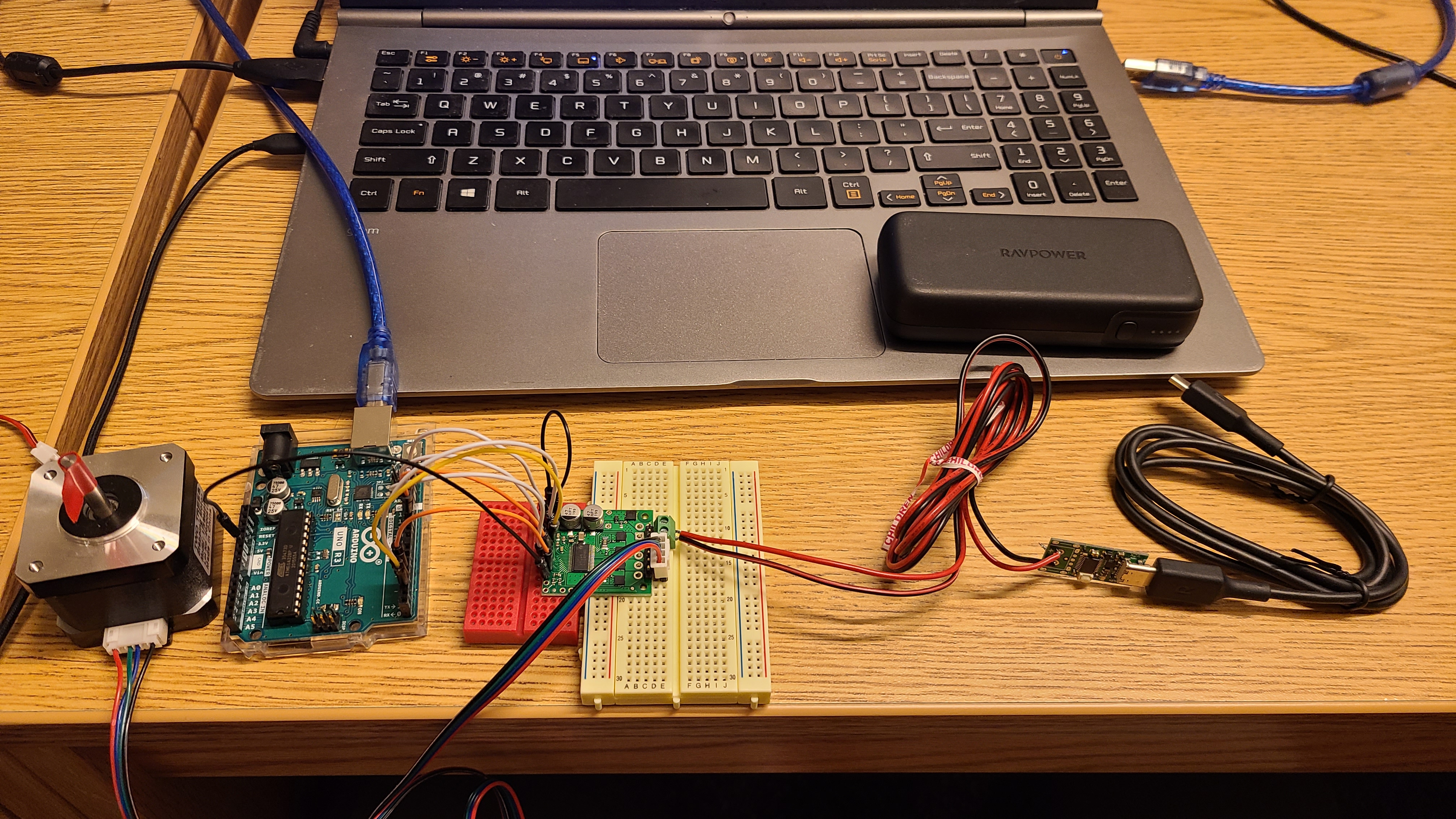
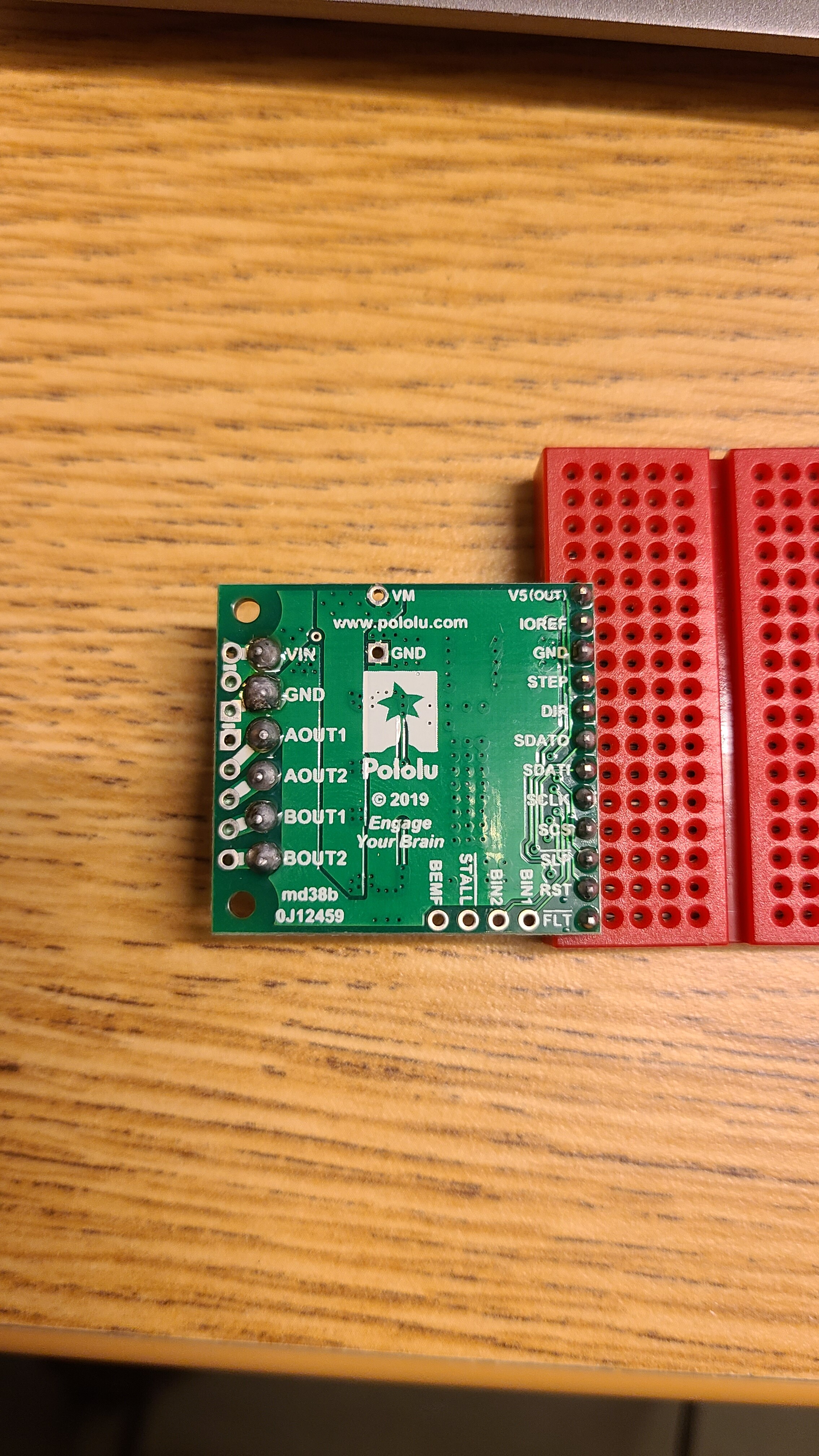
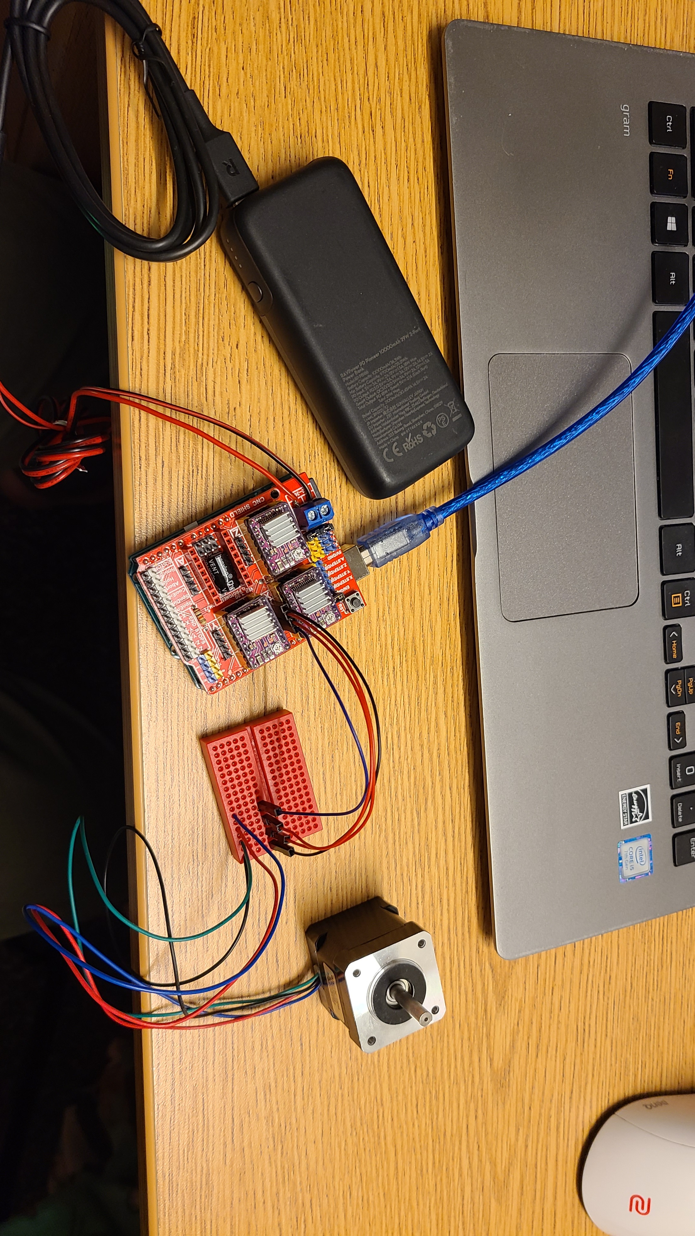
Here is how I wired everything:
NOTES:
V5 (OUT) with IOREF are connected with a jumper wire
!SLEEP is connected to the Arduino Uno 5V source
VIN is supplied with 12V not 8V from a portable battery
I did not solder anything because I wanted to test everything before hand
When I connect a DC 12V fan to the VIN and GND pins on the 36v4, the fan runs normally, but the stepper motor still does not move, stall, or seem to get any power.
// This example shows basic use of a Pololu High Power Stepper Motor Driver.
//
// It shows how to initialize the driver, configure various settings, and enable
// the driver.  It shows how to step the motor and switch directions using the
// driver's SPI interface through the library's step() and setDirection() member
// functions.
//
// Since SPI is used to trigger steps and set the direction, connecting the
// driver's STEP and DIR pins is optional for this example.  However, note that
// using SPI control adds some overhead compared to using the STEP and DIR pins.
// In addition, since the library caches SPI register values, SPI control is
// more likely to re-enable the driver with the wrong settings (e.g. current
// limit) after a power interruption, although using the verifySettings() and
// applySettings() functions appropriately can help prevent this.
//
// Before using this example, be sure to change the setCurrentMilliamps36v4 line
// to have an appropriate current limit for your system.  Also, see this
// library's documentation for information about how to connect the driver:
//   http://pololu.github.io/high-power-stepper-driver

#include <SPI.h>
#include <HighPowerStepperDriver.h>

const uint8_t CSPin = 4;

// This period is the length of the delay between steps, which controls the
// stepper motor's speed.  You can increase the delay to make the stepper motor
// go slower.  If you decrease the delay, the stepper motor will go faster, but
// there is a limit to how fast it can go before it starts missing steps.
const uint16_t StepPeriodUs = 2000;

HighPowerStepperDriver sd;

void setup()
{
  SPI.begin();
  sd.setChipSelectPin(CSPin);

  // Give the driver some time to power up.
  delay(1);

  // Reset the driver to its default settings and clear latched status
  // conditions.
  sd.resetSettings();
  sd.clearStatus();

  // Select auto mixed decay.  TI's DRV8711 documentation recommends this mode
  // for most applications, and we find that it usually works well.
  sd.setDecayMode(HPSDDecayMode::AutoMixed);

  // Set the current limit. You should change the number here to an appropriate
  // value for your particular system.
  sd.setCurrentMilliamps36v4(1700);

  // Set the number of microsteps that correspond to one full step.
  sd.setStepMode(HPSDStepMode::MicroStep1);

  // Enable the motor outputs.
  sd.enableDriver();
}

void loop()
{
  // Step in the default direction 1000 times.
  sd.setDirection(0);
  for(unsigned int x = 0; x < 1000; x++)
  {
    sd.step();
    delayMicroseconds(StepPeriodUs);
  }

  // Wait for 300 ms.
  delay(300);

  // Step in the other direction 1000 times.
  sd.setDirection(1);
  for(unsigned int x = 0; x < 1000; x++)
  {
    sd.step();
    delayMicroseconds(StepPeriodUs);
  }

  // Wait for 300 ms.
  delay(300);
}
Any help would be appreciated! Thank you for your time!
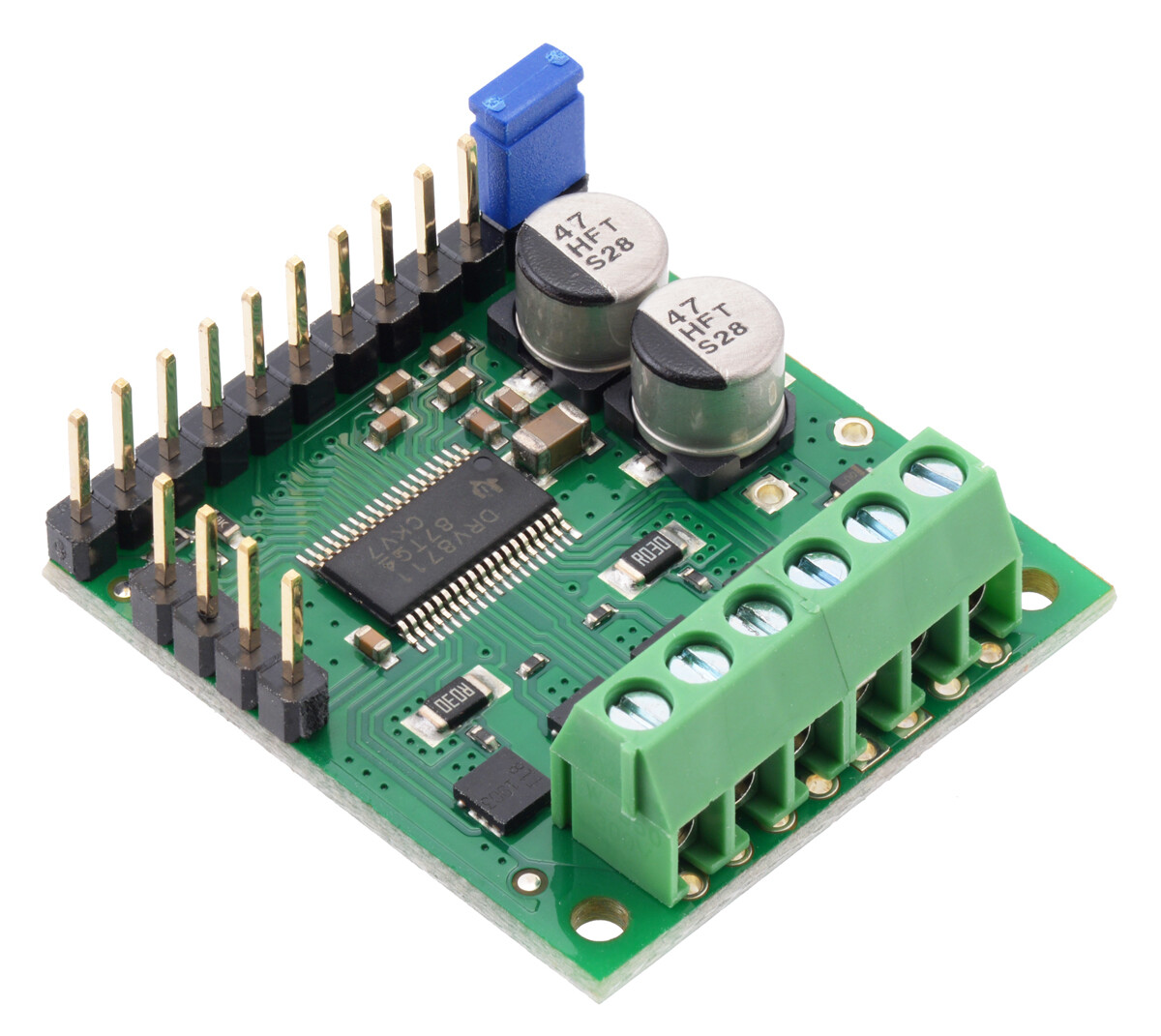
When using jumper wire and breadboard connections, you will need to solder to the board to get any kind of reliable electrical connections; simply pinning the jumper wires through the holes on the board will almost certainly not work reliably.
The male header pins that come with the board can be soldered to the 0.1" pins along the edge of the board opposite the power and motor connections, so you do not have to make permanent connections. You can either solder them facing upward, as shown in the picture below, which is useful when using female jumper wires:
Hello Brandon!
I am still unable to get the motor running. This time I have soldered the pins and used a Pololu - Stepper Motor: Bipolar, 200 Steps/Rev, 35×36mm, 2.7V, 1 A/Phase. I don’t know if this is apart of the issue, but VIN and GND are receiving 12V, however, AOUT1, AOUT2, BOUT2, and BOUT2 are getting 0.67V.
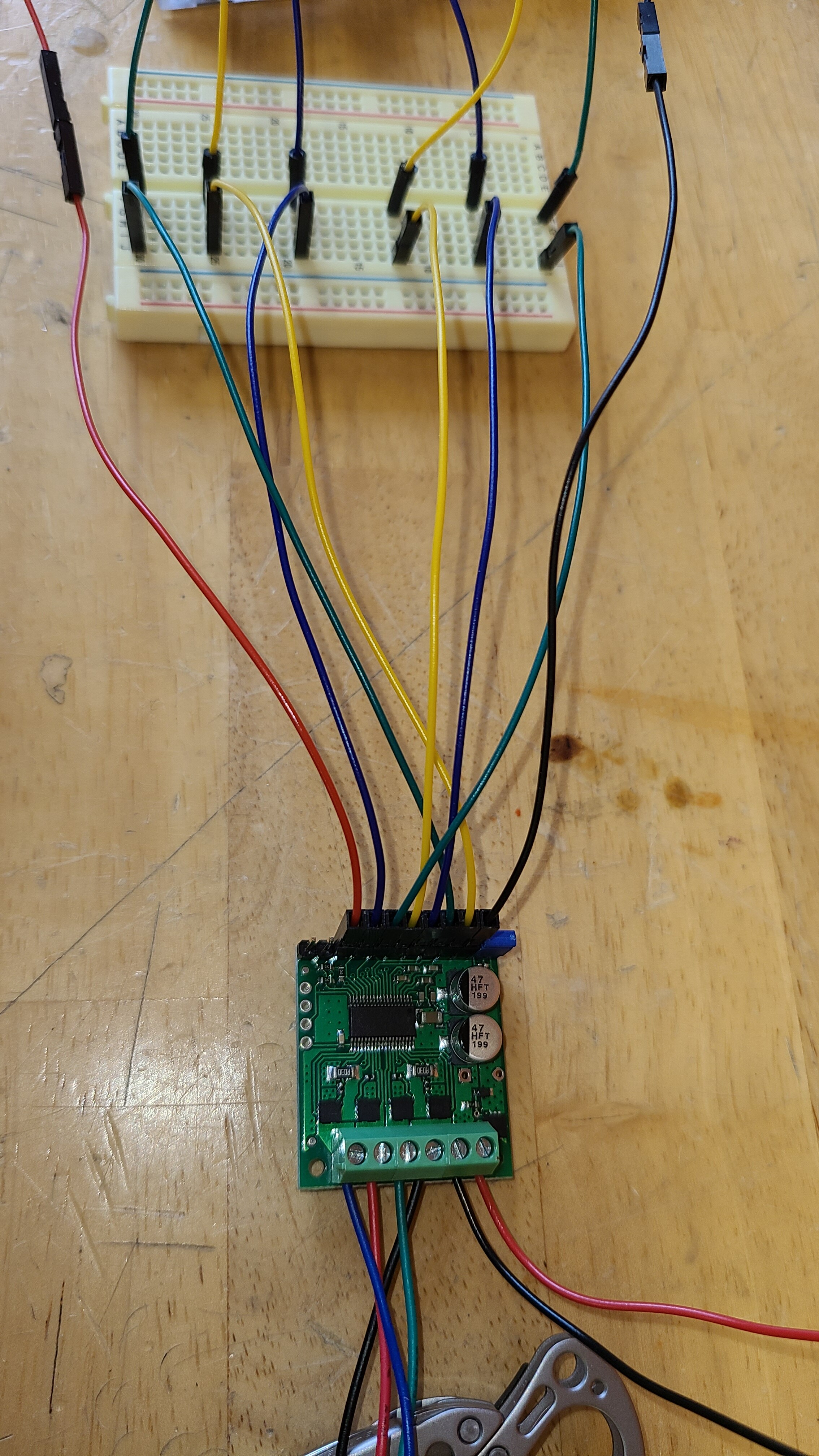
I soldered the male pins as well as the 3 terminal blocks shown below:
(This was my first time soldering so let me know if they are really off)
Here is the adjusted code for the NEMA 14 stepper motor
#include <SPI.h>
#include <HighPowerStepperDriver.h>

const uint8_t CSPin = 4;

// This period is the length of the delay between steps, which controls the
// stepper motor's speed.  You can increase the delay to make the stepper motor
// go slower.  If you decrease the delay, the stepper motor will go faster, but
// there is a limit to how fast it can go before it starts missing steps.
const uint16_t StepPeriodUs = 2000;

HighPowerStepperDriver sd;

void setup()
{
  SPI.begin();
  sd.setChipSelectPin(CSPin);

  // Give the driver some time to power up.
  delay(1);

  // Reset the driver to its default settings and clear latched status
  // conditions.
  sd.resetSettings();
  sd.clearStatus();

  // Select auto mixed decay.  TI's DRV8711 documentation recommends this mode
  // for most applications, and we find that it usually works well.
  sd.setDecayMode(HPSDDecayMode::AutoMixed);

  // Set the current limit. You should change the number here to an appropriate
  // value for your particular system.
  sd.setCurrentMilliamps36v4(1000);

  // Set the number of microsteps that correspond to one full step.
  sd.setStepMode(HPSDStepMode::MicroStep32);

  // Enable the motor outputs.
  sd.enableDriver();
}

void loop()
{
  // Step in the default direction 1000 times.
  sd.setDirection(0);
  for(unsigned int x = 0; x < 1000; x++)
  {
    sd.step();
    delayMicroseconds(StepPeriodUs);

  }

  // Wait for 300 ms.
  delay(300);

  // Step in the other direction 1000 times.
  sd.setDirection(1);
  for(unsigned int x = 0; x < 1000; x++)
  {
    sd.step();
    delayMicroseconds(StepPeriodUs);
  }

  // Wait for 300 ms.
  delay(300);
}
I have also used the BasicStepping code and cannot get the stepper motor to move at all
From what I can tell in your pictures, that soldering looks great, especially for a first timer!
I didn’t notice anything wrong in your wiring or code. Do you get any signs of life from the motor when you run that program (e.g. is it holding its position, buzzing, jittering)? Could you post more information about the stepper motor and power supply you are using?If you have access to a benchtop power supply, could you try using that instead to see if you get different results?
This stepper motor runs at 2.7V and has a 1 A/Phase. It doesn’t have any signs of life when in use. When everything is plugged in, the motor can rotate freely when turning the shaft by hand, it makes zero noise and produces no vibrations. If you want to know anything more specific let me know.
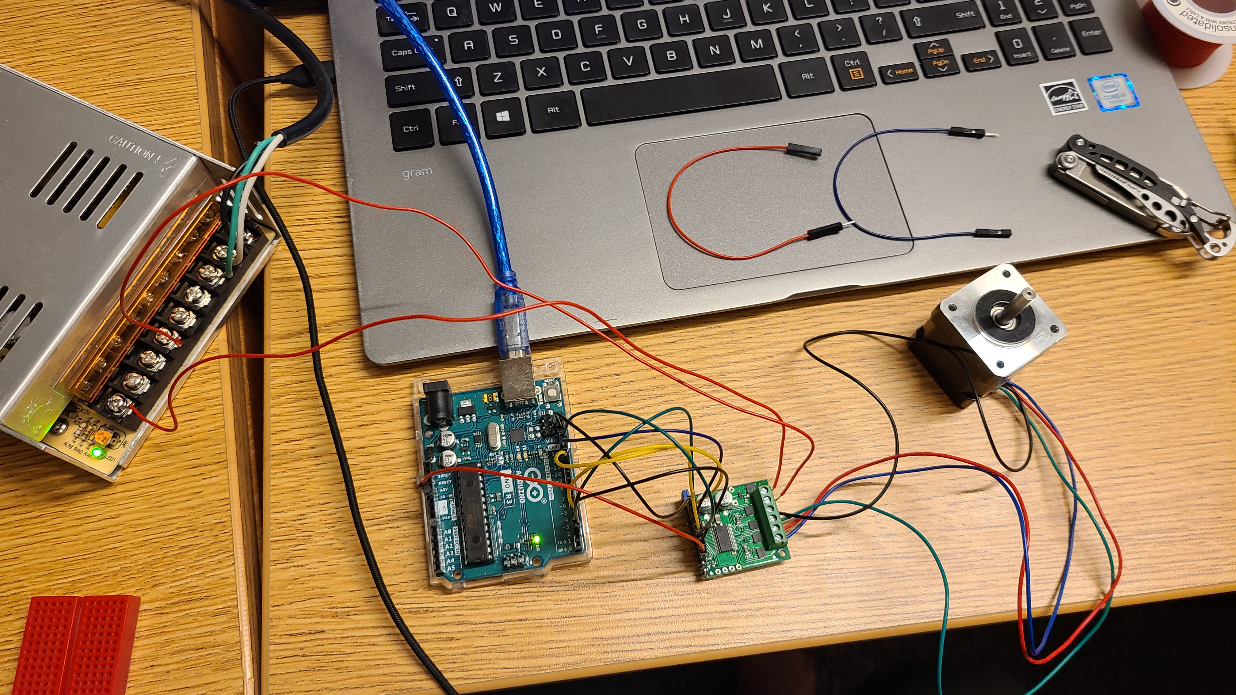
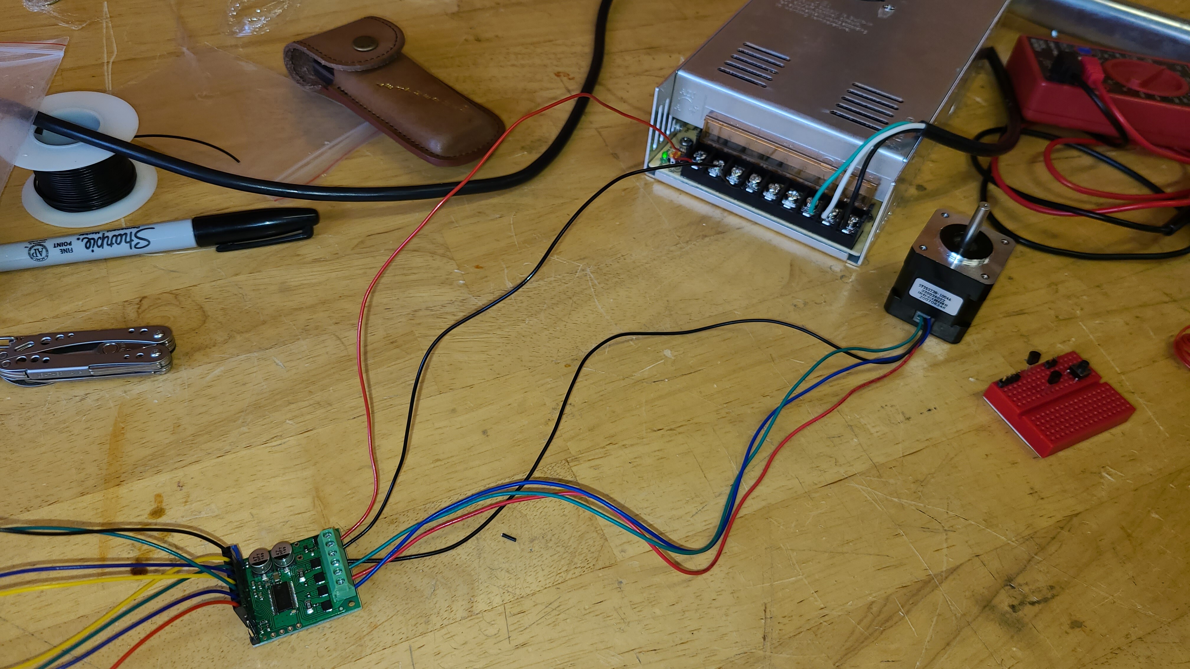
These are the power supplies I have been using/testing/swapping out:
A portable battery with a Power Delivery adapter producing 12V
When I use a CNC shield with a DRV8825 Stepper Motor Driver with the same #1209 stepper motor, the stepper motor runs fine. This also works for all the power supplies mentioned above.
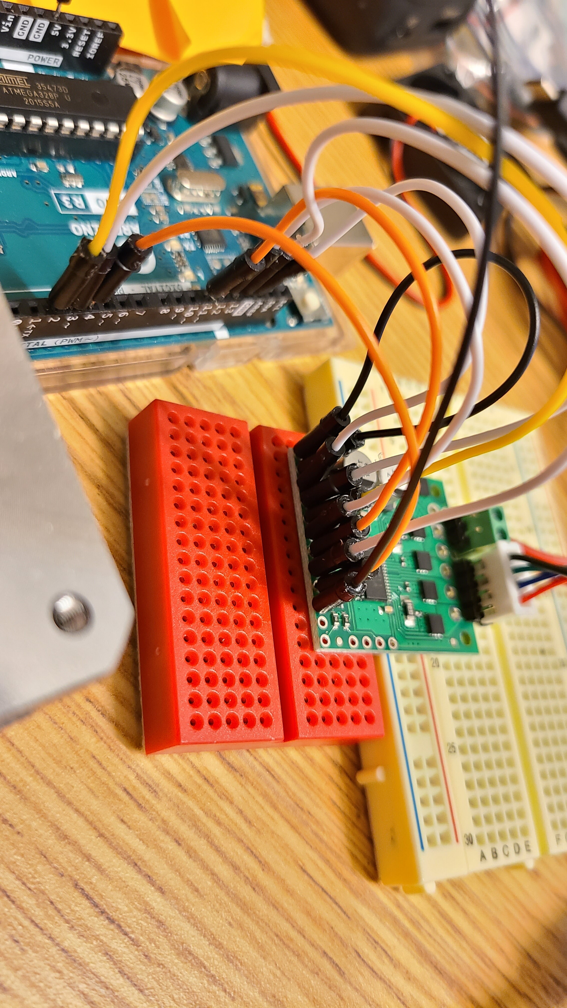
It is more difficult to follow the connections in your updated pictures, but it looks like you might have swapped the DIR and STEP pins on accident. You might also check the SPI connections again; they were particularly hard to follow in the updated pictures, but the diagram your posted in your original post looks correct, so make sure they match that.
If you are still having problems after that, can you post updated pictures that more clearly show all of those connections?
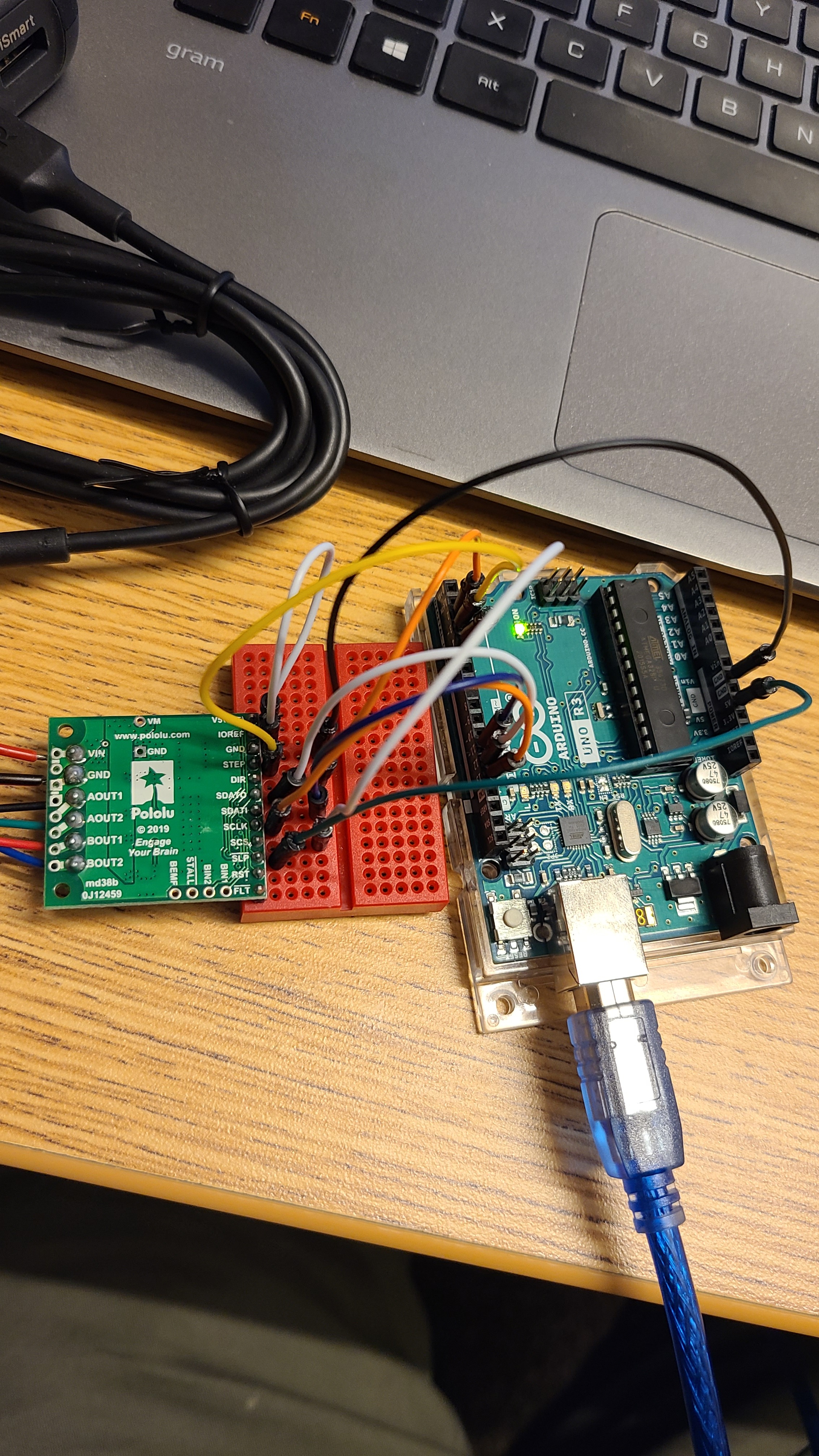
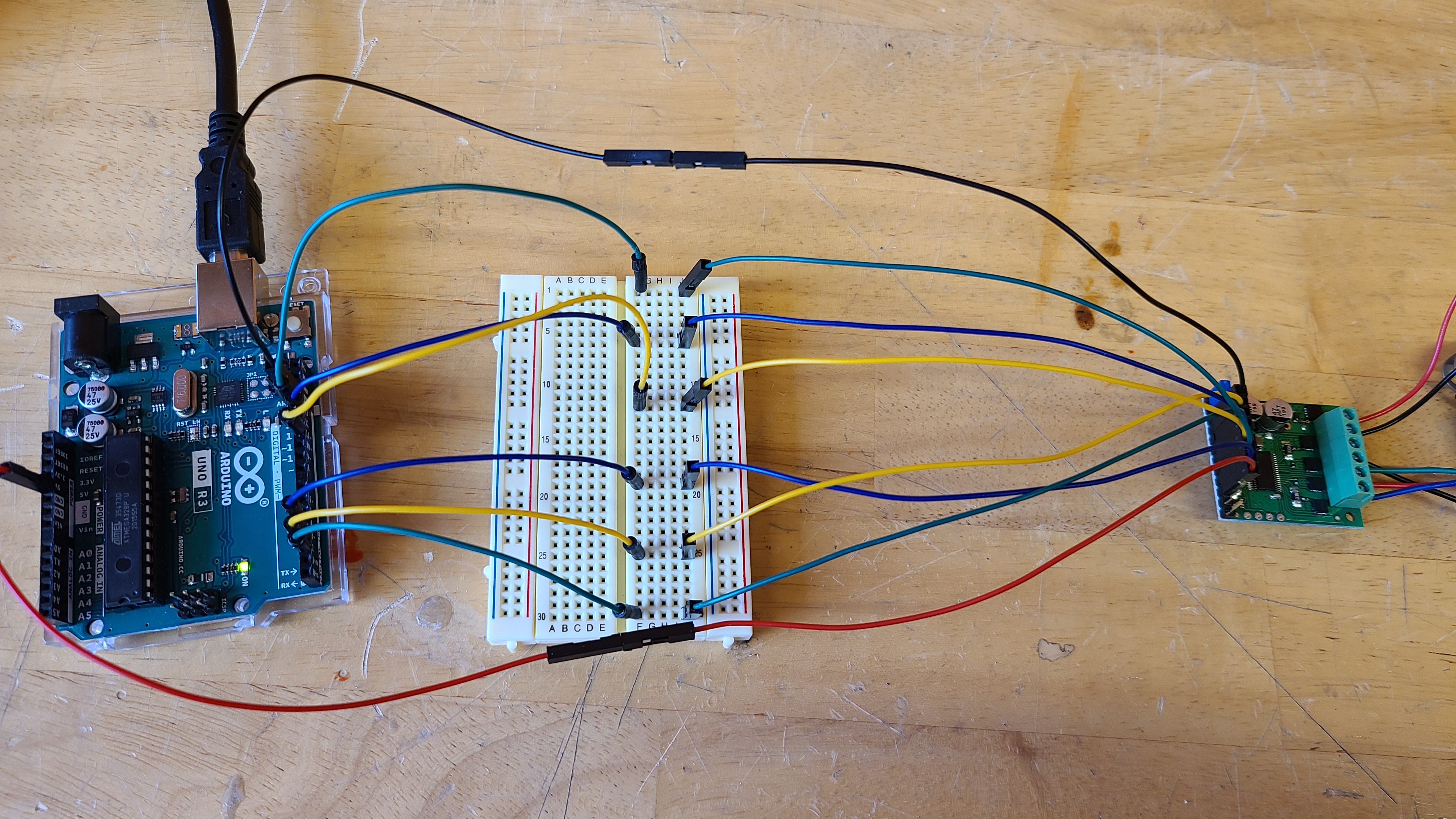
Here is the wiring from the picture above:
IREF <-> 5V (OUT) jumped with blue head pin
ARD GND → BLACK WIRE → GND
ARD D13 → GREEN WIRE → SCLK
ARD D12 → BLUE WIRE → SDATO
ARD D11 → YELLOW WIRE → SDATI
ARD D4 → BLUE WIRE → SCS
ARD D3 → YELLOW WIRE → STEP
ARD D2 → GREEN WIRE → DIR
ARD 5V → RED WIRE → SLEEP
The power source is a 12V power supply plugged into the wall outlet with the RED WIRE to VIN and BLACK WIRE to GND
So no luck again, even if I switch the driver with another 36v4 driver the motor doesn’t run, have any power, stall, etc. I’m not sure if both drivers are faulty at this point, but I know for certain that the power supply, motor, and Arduino work as I tested them separately.
I would be down to meet over Zoom or a call to solve this problem.
Thank you for the updated pictures. We test all of our boards before they ship, so it would be extremely unlucky for you to have somehow gotten 2 bad boards. Did you try to use both of your High-Power Stepper Motor Driver 36v4 boards before soldering them, and has either of them ever worked for you? If both of them are showing the exact same problem, that suggests that something in your setup is a more likely cause.
Could you try uploading the unmodified BasicStepping.ino example to your Arduino and trying it again? If you still get no reaction, can you monitor the voltage on the STEP pin (preferably with an oscilloscope) and make sure it is pulsing as expected while it is running? Additionally, could you measure the voltage at the VM pin as well as the 5V (out) pin on the driver?
On a side note, I find it cool that you guys test everything before you ship them out. I ran the unmodified BasicStepping.ino that you linked and got nothing again.
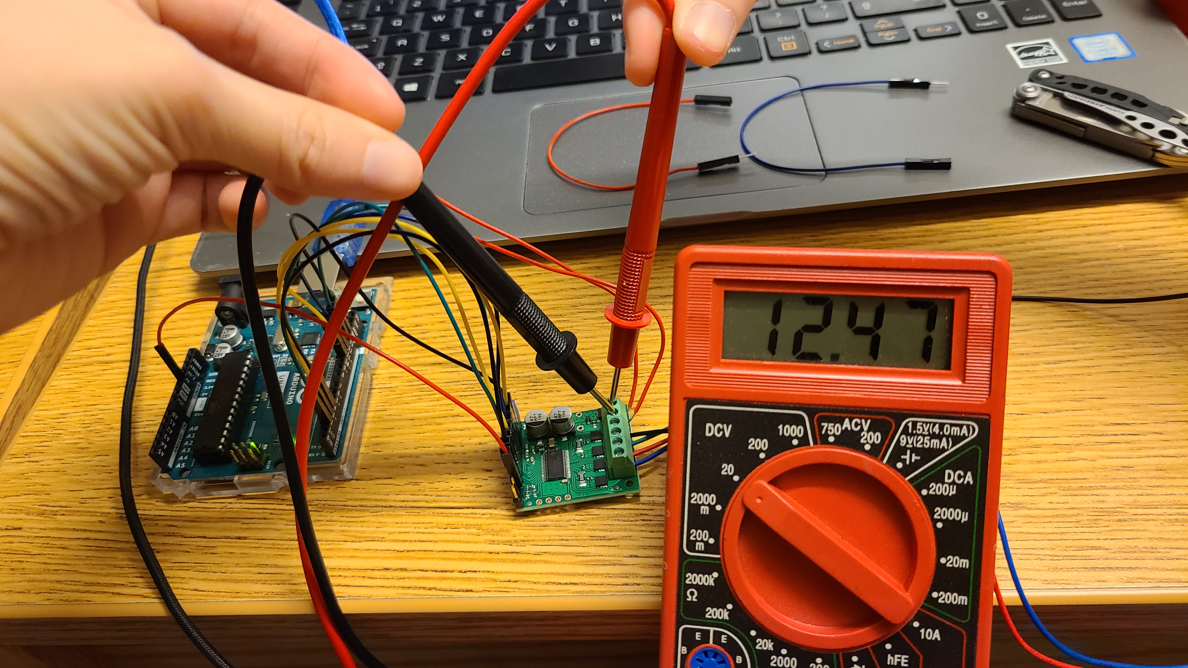
I then measured the following pins per request using a multimeter while running that ino:
STEP pin reads out 0.02V (I’ll talk a little more about this below)
VM reads out 12.41V
5V (OUT) reads out 5.01V
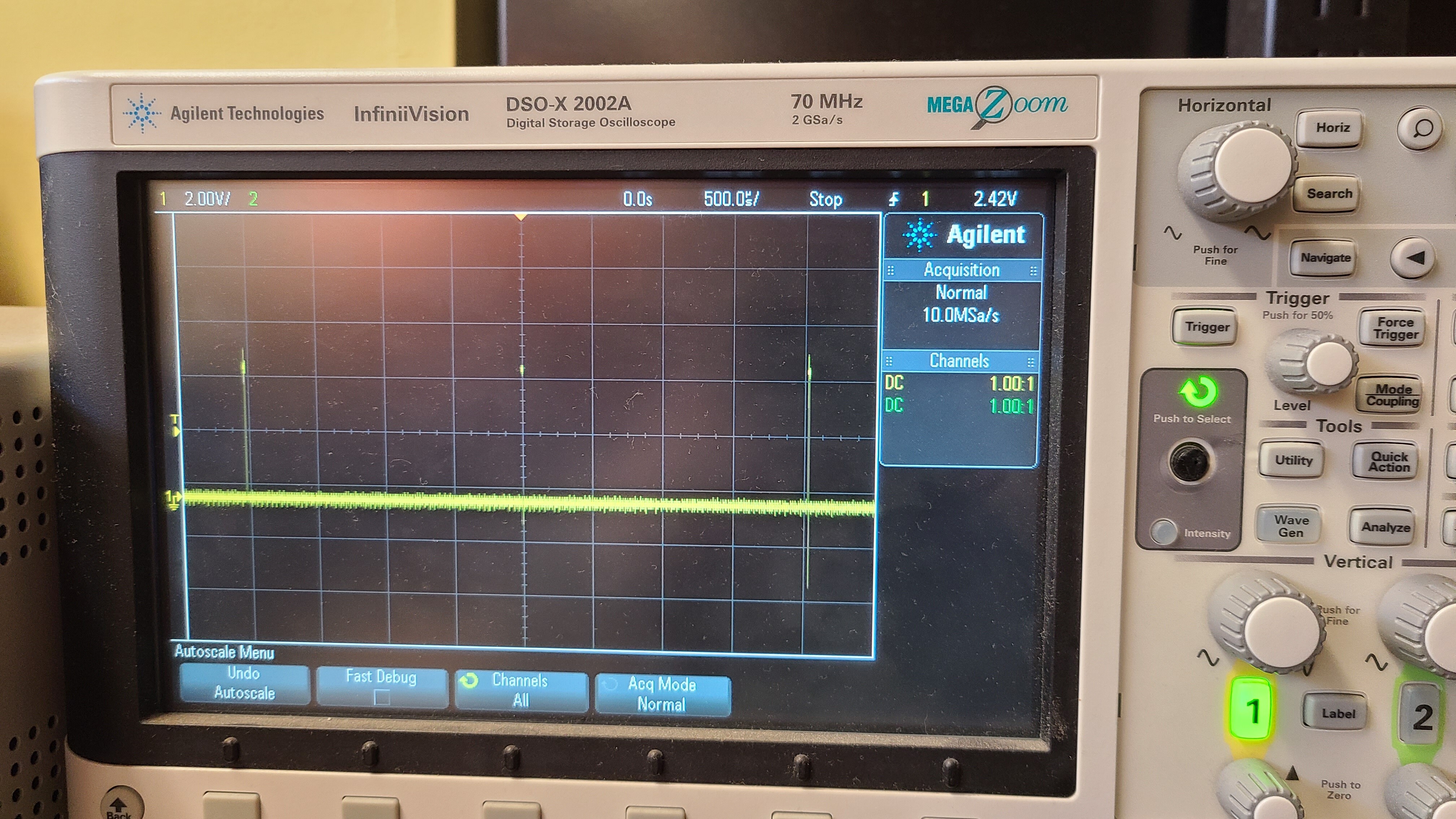
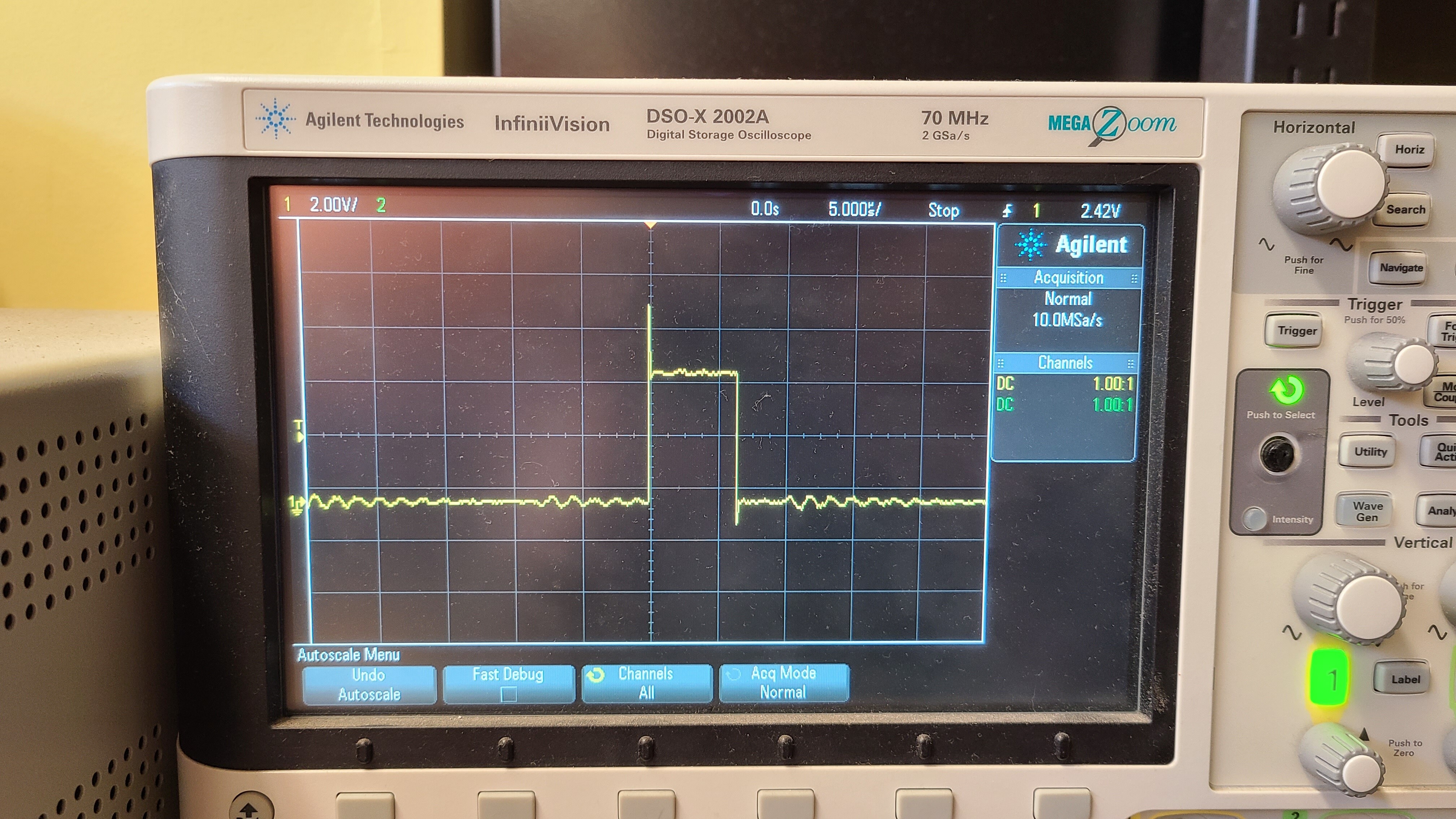
I tried using my school’s oscilloscope, but I am not quite sure what I’m doing/looking for. I followed a video explanation of how to use one and got these results. Take these pictures with a grain of salt.
I see these little jumps which I’m guessing are the pulses (STEP pin):
Thank you for the update and scope pictures. Could you answer whether or not either board ever worked for you and if you tried them both in their un-soldered state? Disconnecting a stepper motor while the system is energized could cause damage to the stepper motor or driver, so I am concerned that either your stepper or both of the boards might have been damaged when they were used un-soldered due to intermittent connections. Could you email us with your order information at support@pololu.com with a reference to this post included as well?
In the meantime, could you try powering down the system, disconnecting the motor, then powering it back up and looking at each of the motor output pins on the board (with respect to ground)?