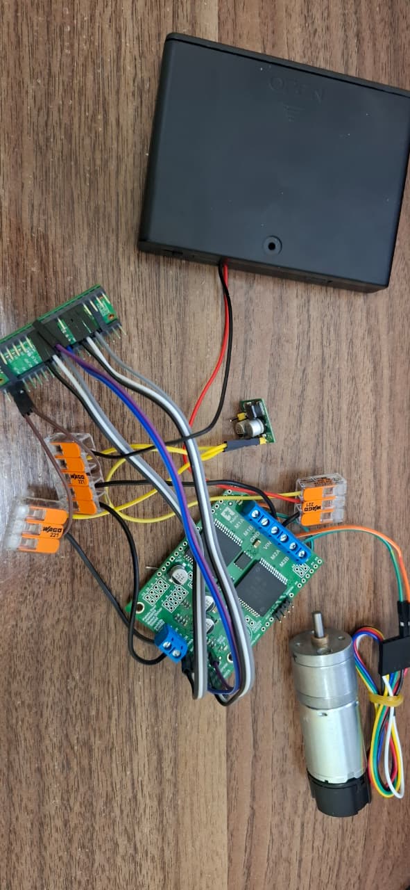
Hi, I am trying to power a 25D metal motor with a Dual VNH5019 Motor Driver Shield for Arduino.
Microcontroller: Raspberry pi pico 2w running Micropython
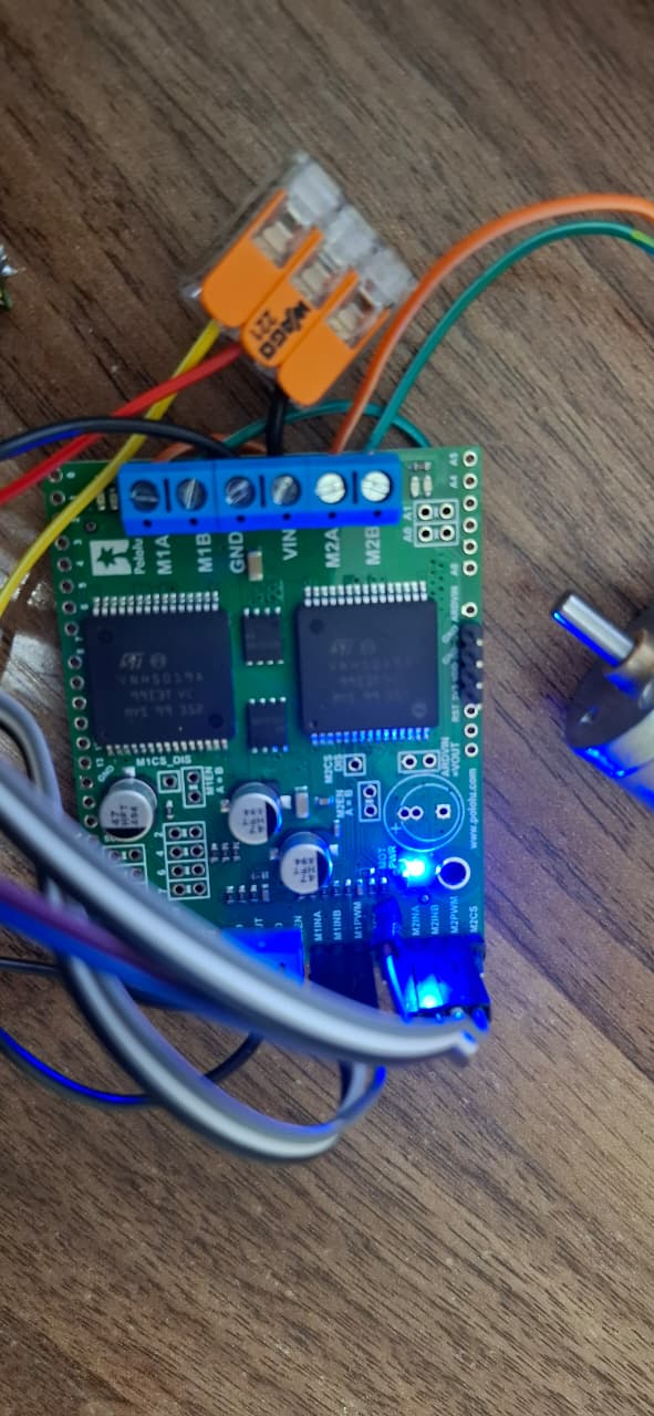
Motor m1 & m2 connected to M2A and M2B on driver.
Logic wiring:
-M2INA connected to GP10
-M2INB connected to GP11
-M2PWM connected to GP12
-Tested with and without M2EN connected to GP9
Power wiring:
-7.2 V NiMH battery connected to Driver VIN
-5V buck powers pico VSYS and driver VDD
-Pico GND, Driver GND, Buck Gnd merge into battery - terminal
When battery switch is closed, the led on the left side of the driver near the additional capacitor hole light up blue. No other lights light up.
The same system (Buck , battery , pico , wires) was tested on the Motoron M2T500 and worked)
Here’s the code i used:
import time
from machine import Pin, PWM

ina = Pin(10, Pin.OUT)
inb = Pin(11, Pin.OUT)

en = Pin(9, Pin.OUT)
en.value(1)

pwm = PWM(Pin(12))
pwm.freq(10000)

try:

    ina.value(1)
    inb.value(0)

    pwm.duty_u16(65535)


    time.sleep(5)

finally:

    pwm.duty_u16(0)
    ina.value(0)
    inb.value(0)
    en.value(0)
    pwm.deinit()
Is there any way to get a Micropython library for VNH5019 or some example code?
Please measure VIN, VDD,GND,M2PWM, M2INA, M2INB with a multimeter while your program is running.
The VIN is 7.8v
VDD: 5V
M2PWM,M2INA,M2INB, M2EN are all 0 v
M2A and M2B are also 0v
Hello.
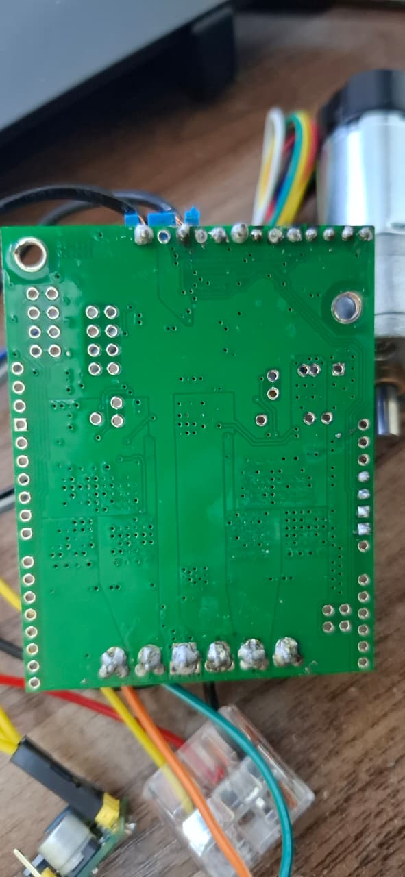
I took a brief look at your code and didn’t notice any obvious problems, but most of your solder joints stand out as potentially suspect and might not be making a solid electrical connection. Could you try reworking them to ensure they are all properly wetting to the pads on the board? Adafruit’s Guide to Excellent Soldering is a great reference for identifying and fixing these common soldering issues.
If you continue having problems after that, could you upload some updated pictures of the soldering and try measuring the voltage on directly on the Raspberry Pi Pico pins while your code is running to see if you get a reading there?
Brandon
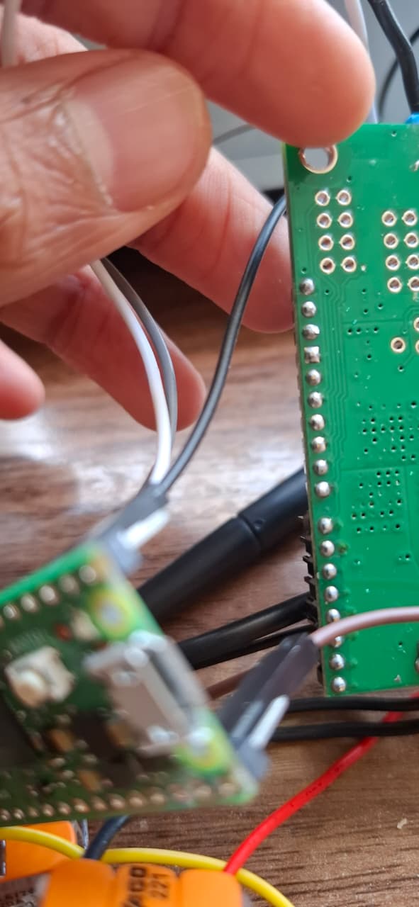
Hi, I soldered new pins into the top pin holes labeled 1 through 12.
Also tried Pico GP2,3,4 instead of 10,11,12
I connected inA to pin 7 on the driver, INB to pin 8 and pwm to pin 10 and tried unplugging the 5v VDD wire and it gave the following readings:
INA- 2.5-3V
INB- 0V
PWM- 2.5-3V
However, when i connect the 5v VDD wire back , none of the logic wires show any readings.
But even with VDD disconnected the motor still doesn’t spin and no output voltage on M2A and M2B.
Here are the newly soldered pins
From your description, it sounds like the VDD pin might be shorted and causing your Raspberry Pi Pico to brownout. Could you measure the resistance between VDD and GND with the system unpowered?
The soldering in your new picture looks good, but to clarify, did you also touch up all of your previous solder joints? Could you post some updated pictures showing both sides of the whole board and soldering as it is now, and also show your connections if they have changed?
Brandon
Hi , thank you so much for your help. Its fixed now
The VDD with the terminal block (the one that I was using) shows a resistance reading very close to 0 (between 0.1 and 0.6)
So, I tried using the ard.VDD pin instead and it worked