Good Evening All,
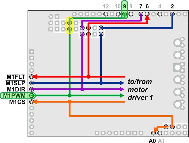
I am currently using a G2 24v14 Pololu and trying to stack it with an Adafruit V2 motor shield and a Arduino Mega. The plan is to control an underwater vehicle with the thruster motor being driven by the G2 and two servos to control direction. The issue I’ve run in to is when I attempt the code with both the motor and the servos, the dc motor doesn’t work. The G2 buzzes and the red and green lights next to the motor input flicker very rapidly. From what I’ve read online, I believe it has something to do with the Servos and the motor both using the same timer. However, when I tried to use a different library for the servo’s that uses timer 2, the buzzing does go away, but the servos now don’t move. I don’t know if maybe I need to assign the AF shield or G2 to use separate timers somehow, or if that is even the correct solution. Any help would be tremendously appreciated. Thanks in advance for all your help! I will also post the code below so maybe it will give a more clear idea of what I’m talking about.
#include "DualG2HighPowerMotorShield.h"
#include <Adafruit_Sensor.h>
#include <Adafruit_BNO055.h>
#include <utility/imumaths.h>
#include <SPI.h>
//include <Servo.h>
#include <ServoTimer2.h>
#include <Adafruit_MotorShield.h>
#include <Wire.h>
#include "IRremote.h"
#include "IRremoteint.h"
#define BNO055_SAMPLERATE_DELAY_MS (100)

Adafruit_MotorShield AFMS = Adafruit_MotorShield(); //Create object motor shield
ServoTimer2 myFinTop;
ServoTimer2 myFinBot;

byte N = 30;
byte runXTimes = 0;
byte servoOneControlPin = 9;
byte servoTwoControlPin = 10;
byte blueLed = 48;
byte redLed2 = 7;
byte redLed = 50;
byte greenLed = 46;
byte remoteSensor = 11;

int servoDelay = 25;
int flag;

float heading;
float pressure;
float finPosition = 75;
float finRight = finPosition*1.50;
float finLeft = finPosition*0.50;
float headError;
float variableHeading;
float rightLimit;
float leftLimit;

DualG2HighPowerMotorShield24v14 md;
Adafruit_BNO055 bno = Adafruit_BNO055();

IRrecv irrecv(remoteSensor);
decode_results results;

void setup() {
/*-------------------------Initiate Common/Servo---------------------*/
//TCCR2B = (TCCR2B& 0xF8)|0x04;

Serial.begin(9600);
pinMode(blueLed,OUTPUT);
pinMode(greenLed,OUTPUT);
pinMode(redLed,OUTPUT);
myFinTop.attach(servoOneControlPin);
myFinBot.attach(servoTwoControlPin);

/*-------------------------Initiate Thruster Motor-------------------*/
  //md.init();
  //md.calibrateCurrentOffsets();
  //delay(10);
  //md.flipM1(true);   // Uncomment to flip a motor's direction

/*-------------------------Initiate IMU------------------------------*/
Serial.println("Orientation Sensor Raw Data Test"); Serial.println("");
  if(!bno.begin())      // Initialize IMU
    {
      Serial.print("NO SIGNAL FROM IMU");
      while(1);
    }
delay(1000);
bno.setExtCrystalUse(true);
Serial.println("Calibration status values: 0=uncalibrated, 3=fully calibrated");

/*------------------------Initiate IR--------------------------------*/
irrecv.enableIRIn(); //Start receiver
}

void loop()
{
  if(irrecv.decode(&results))
  {
    translateIR();
    irrecv.resume();
  }
    calibrate();
    calibrationDisp();
    headingCorrection();
    delay(100);

}

void translateIR()
{
  Serial.println(results.value,DEC);
  switch(results.value)
  {
    case 1637879537:
    thrusterOn();
    break;

    case 1637912177:
    thrusterOff();
    break;
  }
}

void calibrate()
{
  imu::Vector<3> euler = bno.getVector(Adafruit_BNO055::VECTOR_EULER);
  uint8_t system, gyro, accel, mag = 0;
  bno.getCalibration(&system, &gyro, &accel, &mag);

/*-----------------------IMU Sensor----------------------------------*/
// -CHANGE VECTOR_ to CHOICE:
// - VECTOR_ACCELEROMETER - m/s^2
// - VECTOR_MAGNETOMETER  - uT
// - VECTOR_GYROSCOPE     - rad/s
// - VECTOR_EULER         - degrees
// - VECTOR_LINEARACCEL   - m/s^2
// - VECTOR_GRAVITY       - m/s^2

 if(gyro == 3 && mag == 3 && system == 3)         //&& accel == 3
  {
        if(runXTimes < N)
        {
           getHeading();
           runXTimes++;
        }
    delay(100);
    Serial.print("Heading: ");
    Serial.print(heading);
    Serial.println(" Degrees");
  }
/* Display the floating point data */
Serial.print("X: ");
Serial.print(euler.x());
delay(50);

//  Serial.print(" Y: ");
//  Serial.print(euler.y());
//  Serial.print(" Z: ");
//  Serial.print(euler.z());
//  Serial.print("\t\t");

/* Display calibration status for each sensor. */
bno.getCalibration(&system, &gyro, &accel, &mag);
Serial.print(" CALIBRATION: Sys=");
Serial.print(system, DEC);
Serial.print(" Gyro=");
Serial.print(gyro, DEC);
Serial.print(" Accel=");
Serial.print(accel, DEC);
Serial.print(" Mag=");
Serial.println(mag, DEC);
delay(BNO055_SAMPLERATE_DELAY_MS);

}

void headingCorrection()
{
  imu::Vector<3> euler = bno.getVector(Adafruit_BNO055::VECTOR_EULER);
  uint8_t system, gyro, accel, mag = 0;
  bno.getCalibration(&system, &gyro, &accel, &mag);

rightLimit = heading*-0.05;
leftLimit = heading*0.05;
headError = heading - euler.x();
//variableHeading = headError + heading;

  if(rightLimit < headError && headError < leftLimit)
    {
      Serial.println("Status: On Course");
      Serial.print("Heading Error: ");
      Serial.print(headError);
      Serial.println(" degrees");
      myFinTop.write(finPosition);
      myFinBot.write(finPosition);
      Serial.println(" ");
    }
  else if(headError < rightLimit)
    {
      myFinTop.write(finRight); //Counter Left Drift - Top Fin
      myFinBot.write(finRight); //Counter Left Drift -  Bottom Fin
      Serial.print("Heading Error: ");
      Serial.print(headError);
      Serial.println(" degrees");
      Serial.println("Status: Correction left");
      Serial.println(" ");
    }
  else if(headError > leftLimit)
    {
      myFinTop.write(finLeft); //Counter Left Drift - Top Fin
      myFinBot.write(finLeft); //Counter Left Drift -  Bottom Fin
      Serial.print("Heading Error: ");
      Serial.print(headError);
      Serial.println(" degrees");
      Serial.println("Status: Correction right");
      Serial.println(" ");
    }
  else if(heading < 10 && heading >= 351)
    {

    }

}

void calibrationDisp()
{
  imu::Vector<3> euler = bno.getVector(Adafruit_BNO055::VECTOR_EULER);
  uint8_t system, gyro, accel, mag = 0;
  bno.getCalibration(&system, &gyro, &accel, &mag);

    if(gyro == 3 && mag == 3 && system == 3)            //&& accel == 3
    {
      digitalWrite(greenLed,HIGH);
      delay(50);
      digitalWrite(greenLed,LOW);
      digitalWrite(blueLed,LOW);
      digitalWrite(redLed,LOW);
      digitalWrite(redLed2,LOW);
    }
    else if(gyro == 3 && mag == 3)
    {
      digitalWrite(blueLed,HIGH);
      delay(50);
      digitalWrite(blueLed,LOW);
    }
    else if(accel == 3)
    {
      digitalWrite(redLed2,HIGH);
      delay(100);
      digitalWrite(redLed2,LOW);
    }
    else if(system == 3)
    {
      digitalWrite(redLed,HIGH);
      delay(50);
      digitalWrite(redLed,LOW);
    }

}

float getHeading()
{
  imu::Vector<3> euler = bno.getVector(Adafruit_BNO055::VECTOR_EULER);
  uint8_t system, gyro, accel, mag = 0;
  bno.getCalibration(&system, &gyro, &accel, &mag);

  if(gyro == 3 && mag == 3 && system == 3)          //&& accel == 3
  {
    heading = euler.x();
    return(heading);
    delay(100);       //This is new
  }

}

void thrusterOn()
{
  md.enableDrivers();
  delay(1);
  md.setM1Speed(500);
  Serial.print("M1 current: ");
  Serial.println(md.getM1CurrentMilliamps());
}

void thrusterOff()
{
  md.enableDrivers();
  delay(1);
  md.setM1Speed(0);
  Serial.print("M1 current: ");
  Serial.println(md.getM1CurrentMilliamps());
  irrecv.resume();
}

