For my design class in school we are building a robot drive train using 4 go bilda yellow jacket motors hooked up to 2 12v batteries and 2 pololu vnh5019 motor drivers. Our microcontroller is a standard ESP32 that I’ve programmed with a simple code that turns on all four motors as soon as a switch is flipped within the circuit.
Currently when we run the code only 2 of the four motors run, one on each motor driver. We checked all wiring and pin connections to ensure batteries and motors are properly connected back to the esp32, but still haven’t found any errors.
Not sure if I’m dealing with a code issue or an electronics issue but any ideas would be helpful for troubleshooting/debugging
Hello.
If you could post the following details about your setup, I would be happy to help you troubleshoot:
- some pictures of your setup that show all of your connections
- a wiring diagram
- the simplest, but complete, code that exhibits the problematic behavior
- specifications for your motors and batteries (preferably links to product pages or datasheets)
Also, to avoid confusion, can you clarify if you are using 2x of the Dual VNH5019 Motor Driver Shields or 2x of the VNH5019 Motor Driver Carrier
Brandon
Hi Brandon!
Thank you so much for your response. I’ve included more details below…
-
We are using the dual VNH5019 Motor Driver Shields
-
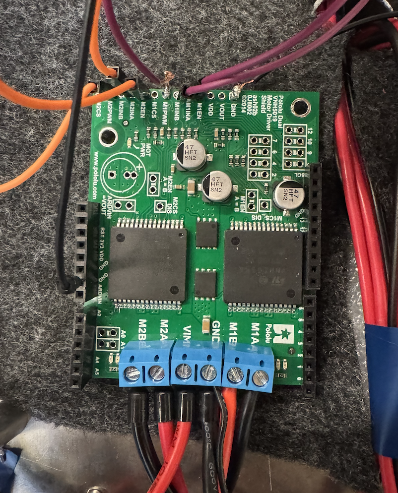
Each of the two drivers is hooked up to a 12V battery through its Vin and GND port, and then hooked into the motors between M1A, M1B, and M2A, M2B, respectively. We’ve soldered the EN, PWM, and IN pins for each of the two motors, as well as the ground. Additionally, we added a common ground on the right-side terminal for the battery. This setup can be seen in the attached photo below
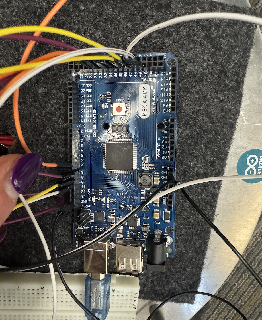
- We ended up switching to an Arduino Mega ADK instead, with pin connections as pictured in the photo below…
We’ve had lots of success with the first motor driver pictured (orange and purple pins) but very little success with the second motor driver. The motor with the yellow wiring worked at one point, but now no longer works. We’ve tested the voltage coming out when the code is run, and there is zero Vout. Because of this we believe the driver is faulty. Is there any other way to fix this.
I have outlined a few of my observations/concerns below:
-
It looks like you are not supplying power to VDD, which powers the internal pull-ups on the enable lines. To enable the motor channels, you should supply this with your logic level voltage (i.e. 3.3V from your Raspberry Pi or 5V from your Arduino).
-
It looks like you are not connecting to the M1INB and M2INB pins on your second board. Please note that these inputs are floating by default and required to reliably control the direction of the motor. I recommend reading through the “Board Connections” sub-section of the “USing as a General-Purpose Motor Driver” section of the shield’s user’s guide. You can also reference the truth table for the motor outputs on page 14 of the VNH5019 driver’s datasheet.
-
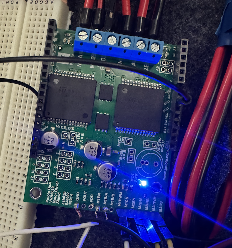
The soldering on the stranded wire (in both pictures) is concerning; it looks like there are some cold solder joints and the solder is not wetting properly to the pads on several pins. Additionally, you have a lot of excess stranded wire that could easily short to neighboring pins. I recommend reworking the solder joints and if you are going to solder the stranded wire directly to the pins like that, making sure that the wire is pushed in up to the insulation, then trimming the excess. Could you post some close-up pictures of the underside of the boards as well?
-
It looks like you have the boards sitting on some kind of carpeted surface; if that’s the case, please note that carpet can build up static electricity, which could discharge and damage electronics. I highly recommend using something like an anti-static mat (or at least moving them to a non-conductive surface like wood or plastic).
Brandon