Help for moving a bipolar step motor!

hello, can i have help for using a bipolar stepped motor ?

i am trying to use a bipolar stepped motor for the first time with this materials :
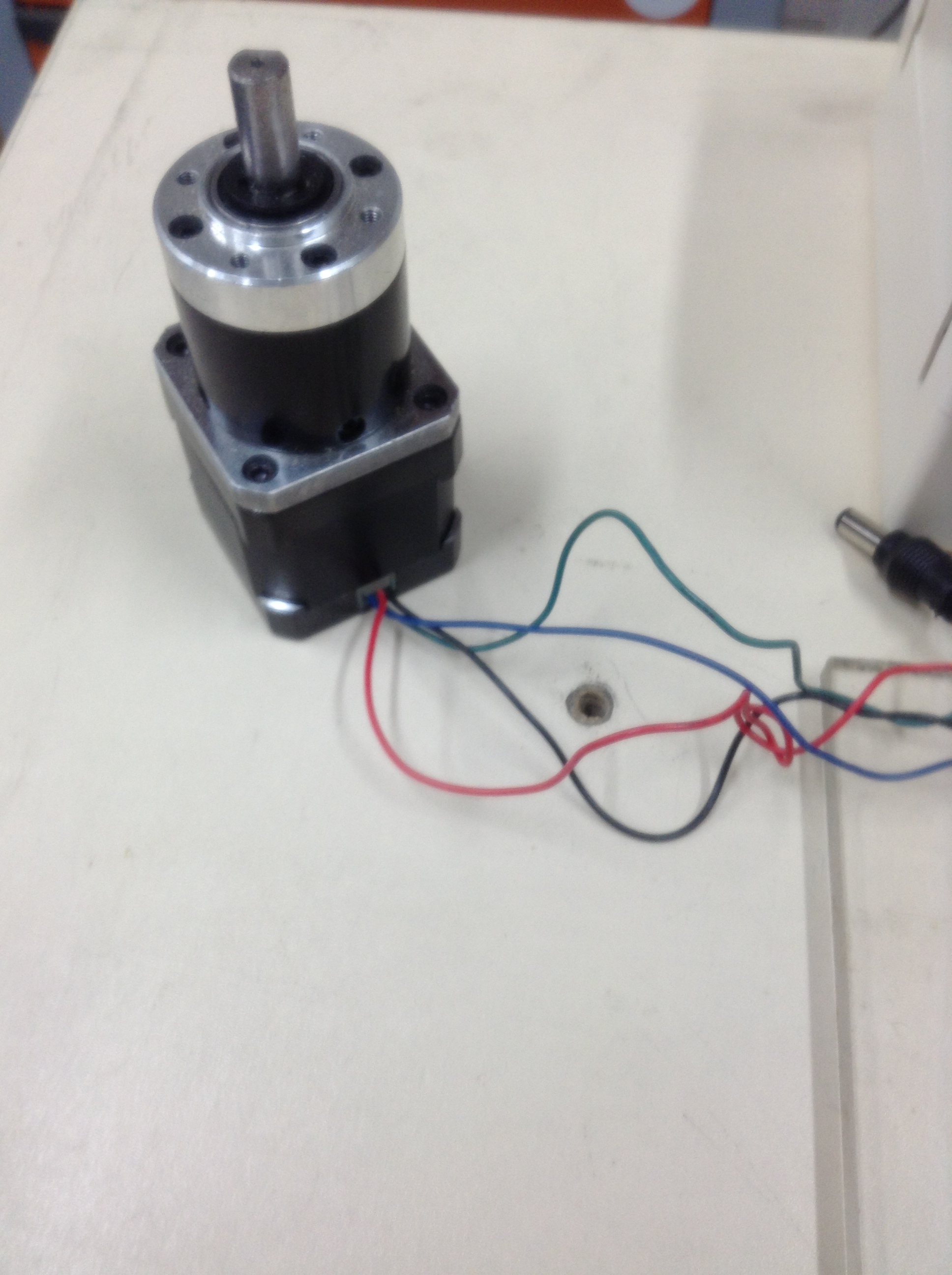
a bipolar stepped motor, 12v, 1.6A, 416 0z-in geared bipolar stepped motor réf : RB-Phi-132
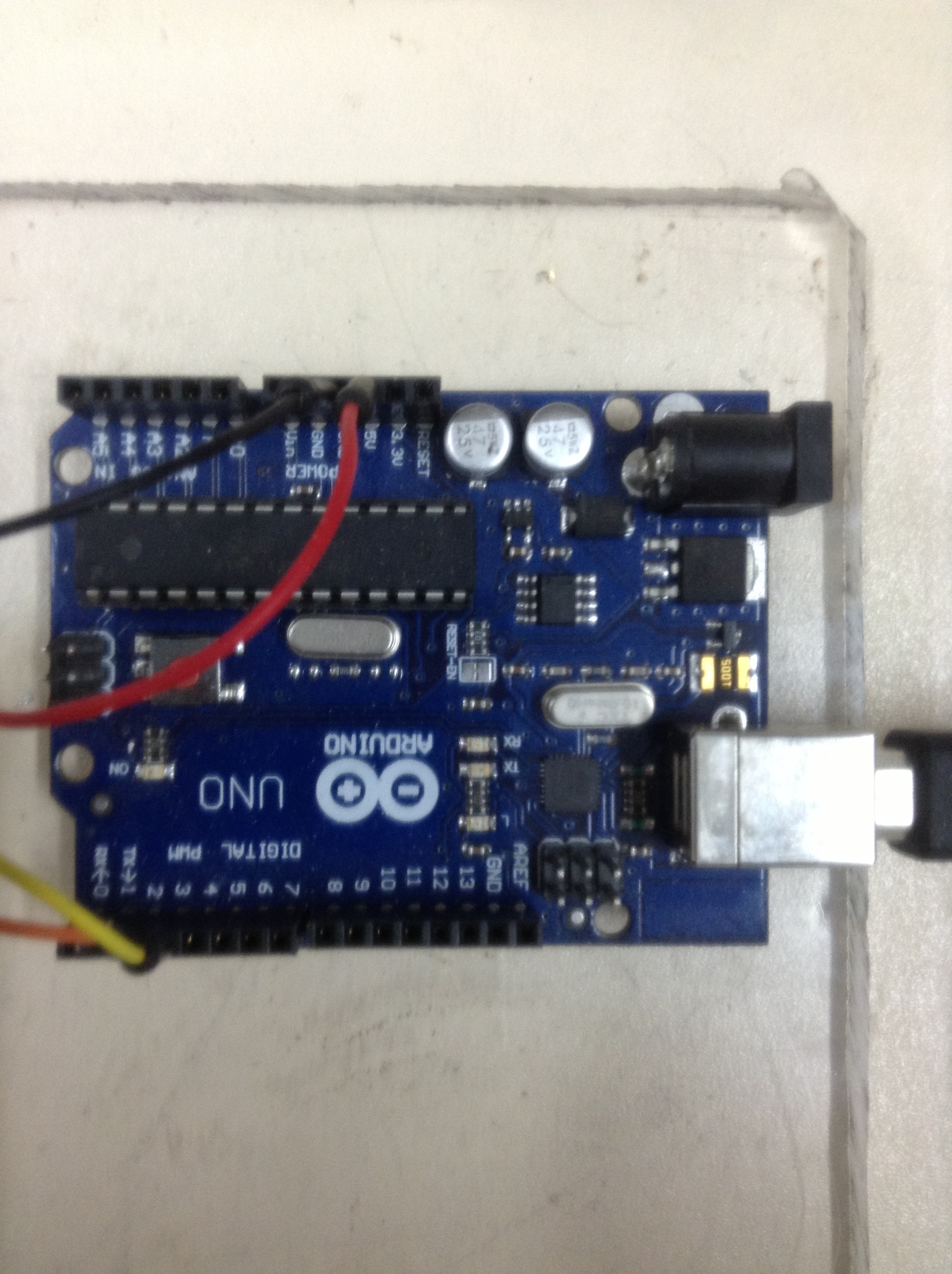
a microcontroller fez cobra 1 réf : RB-Ghi-12 (or with an arduino uno)
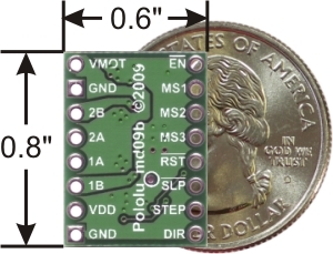
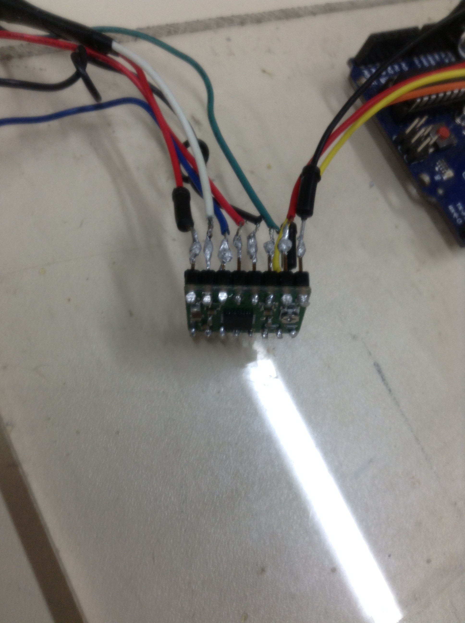
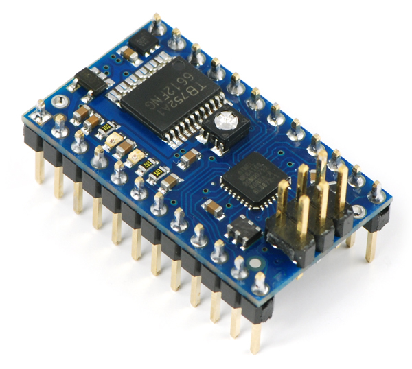
a pololu 2A single bipolar stepper motor driver A4988 réf : RB-Pol-176
a 25w adjustableswitching regulator réf : DE-SWADJ 3A

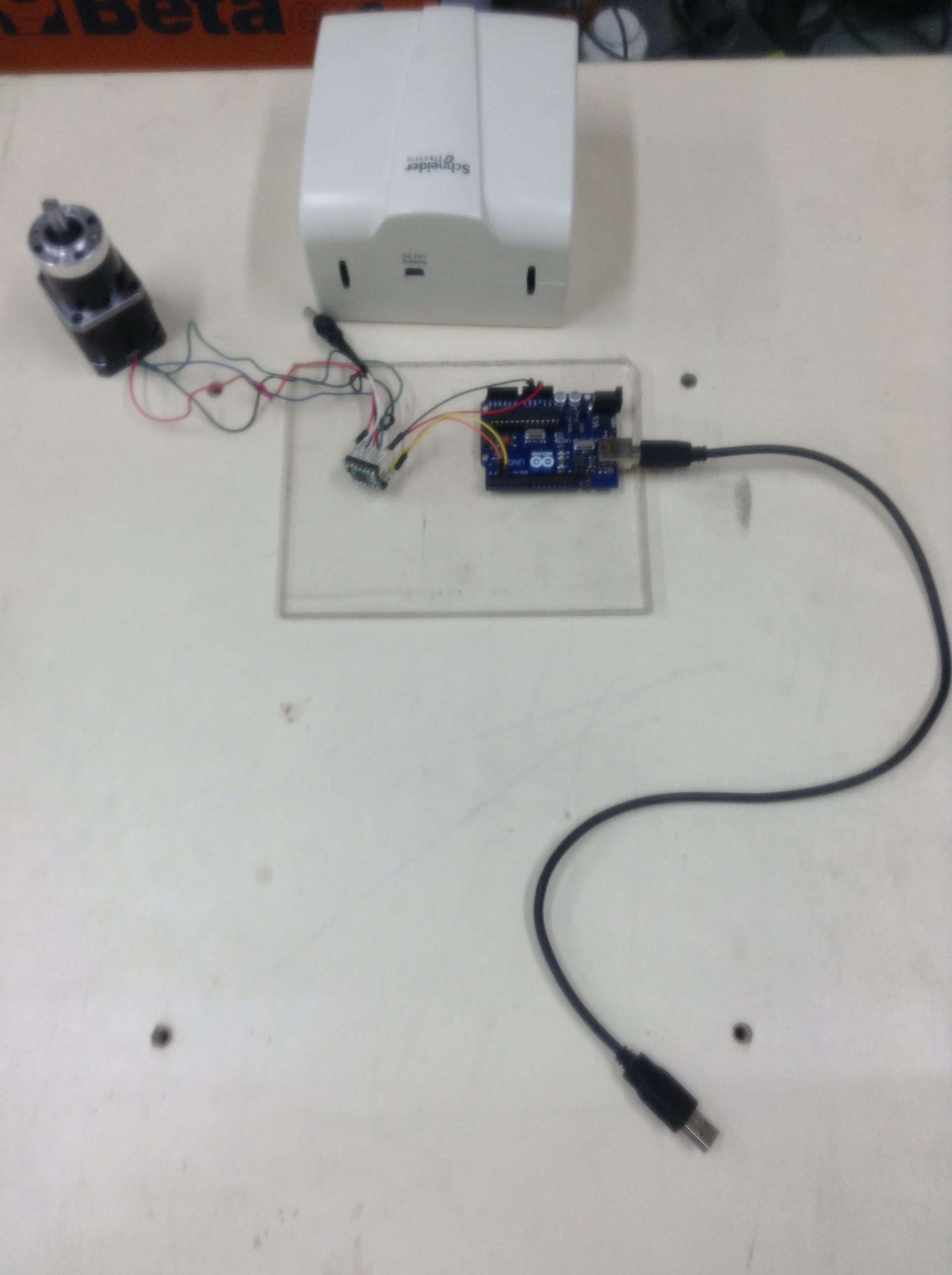
I have tried with arduino uno the pololu schematic given like this:
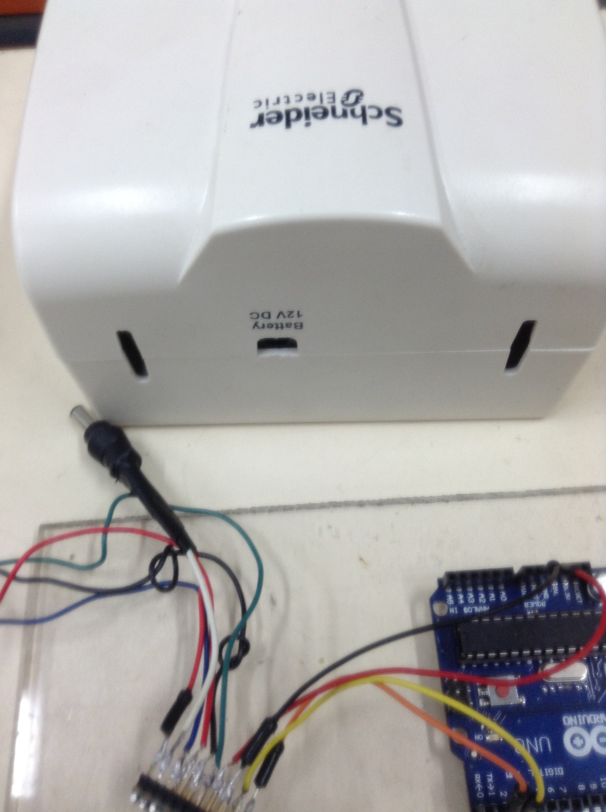
Vmot and gnd to motor power supply (dc 12v)
1a (black) 2a(red) 1b(green) 2b(blue) to the stepped bipolar motor
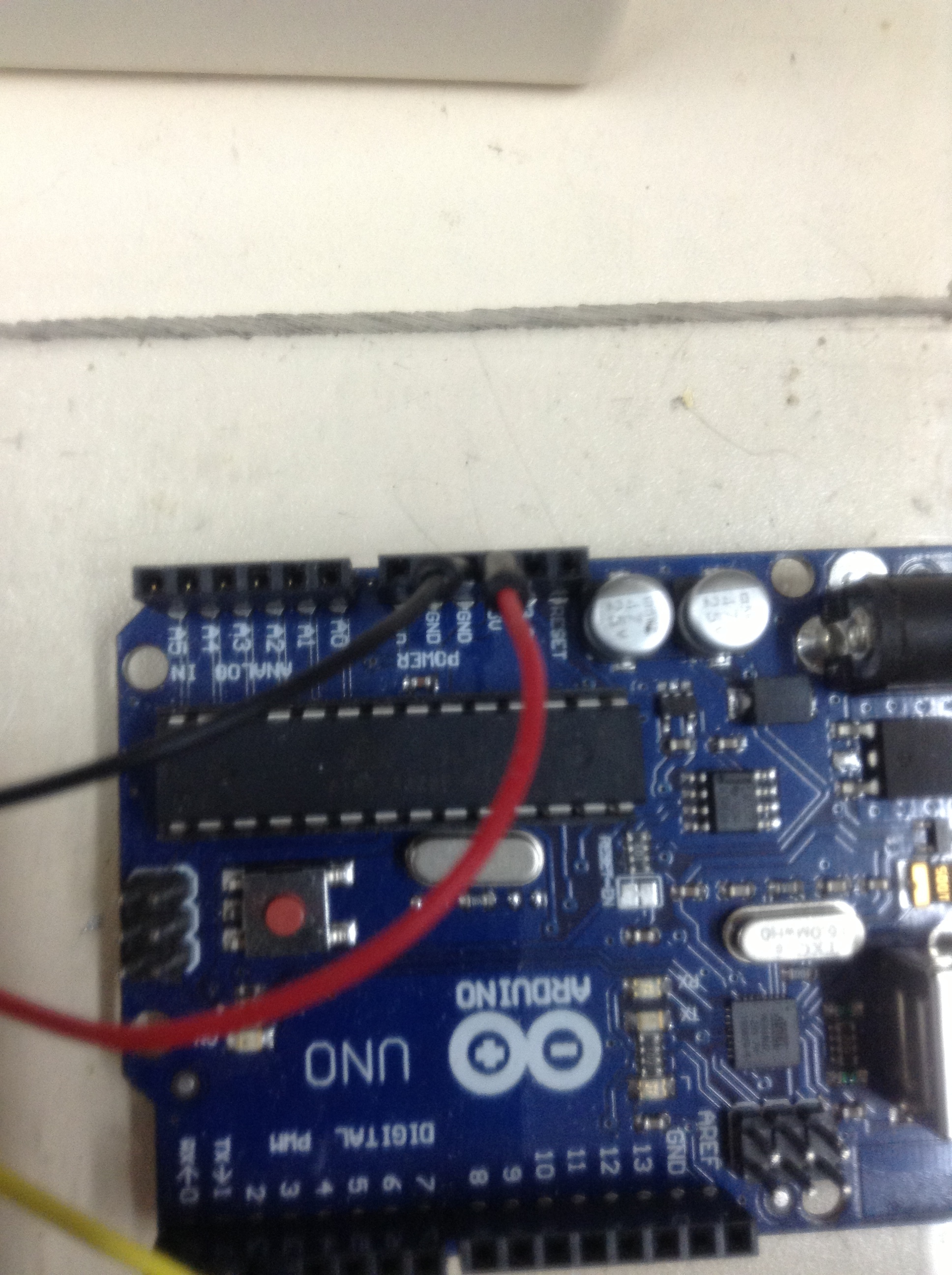
Enable, Step and Dir to the microcontroller arduino (on d13, d12 , d11)

I tried as well to used the d-swadj regulator with a 12v battery, but the motor did not moved.
Here is the code i used :
/*
Test moteur PAP (pas entier)
Carte Pololu avec puce A4988 + régulateur de tension > pololu.com/catalog/product/1183
Ch.Aubert Déc.2011
/
/
************* Définition des E/S *************************/
const int dirPin = 11; // DIR
const int stepPin = 12; // STEP
const int enablePin = 13; // ENABLE

void setup()
{
pinMode(enablePin, OUTPUT); // broche Enable en sortie
digitalWrite(enablePin, HIGH); // ensuite on met un niveau haut sur Enable pour relacher le moteur
pinMode(stepPin, OUTPUT); // Dir et Step en sortie
pinMode(dirPin, OUTPUT);
calibrate(); // lance le stall moteur Ampérage max !
//test(); // lance le test !!
}
void loop()
{
// rien pour l’instant !
}
void calibrate() // Stall moteur Ampérage max !
{
digitalWrite(enablePin, LOW); // active le moteur (il ne sera plus possible de le tourner à la main et l’ampérage sera à son MAX !!
}
void test() // faire tourner le moteur 200 pas
{
int j;
digitalWrite(enablePin, LOW); // active le moteur (il ne sera plus possible de le tourner à la main et l’ampérage sera à son MAX !!
delayMicroseconds(2); // on donne un très court délais par précaution avant de tourner
digitalWrite(dirPin, HIGH); // Tourner à droite (selon branchements !)
for(j=0; j<=199; j++) { // ajuster le nb. de pas (ici 200 pas soit un tour. On compte le zéro !)
delay(200); // ajuster le tempo entre chaque pas (plus le délais est court, plus le mouvement est fluide ! On peut aussi supprimer ce délais !)
digitalWrite(stepPin, LOW);
delayMicroseconds(10); // à ajuster selon moteur, on peut essayer de diminuer à 2 us
digitalWrite(stepPin, HIGH);
delayMicroseconds(1000); // fréquence à ajuster selon moteur (contrôle la vitesse et le couple)
}
digitalWrite(enablePin, HIGH); // On relache le moteur (on peut le tourner à la main)
}

Hello.

Could you first verify that the motor driver and stepper motor are working without the Arduino? This could be done by setting the DIR pin high and switching the STEP pin between high and low and seeing if the motor steps.

- Jeremy

thank’s, how can i put in high and low level with arduino?
do i use another circuit or use the vdd and gnd’s driver?

do i branch directly to the batterry (12v) vmot and gnd + a 100microfarad condo ?

You can use the 5V and GND pin to toggle between high and low for the step input.

i tried to do this experience with:

the 12v dc batterry on vmot and gnd
the stepped motor on 1a(black) 1b(green) 2a(red) 2b(blue)
vdd and gnd on 5v and gnd of the microcontroller
dir put on hig
step on high then low alternatively

But it didn’t make the stepper motor moved.

is there a mistake on the way i did it?
or any other way of testing the stepper motor thne the driver?

i am using this A4988 pololu driver:


Could you please verify that the coil pairs you choose are correct? You can find out which wires are to be connected by checking the datasheet of your stepper motor or by measuring the resistance between the wires. The coil pairs should have low resistance (about 7.5 ohms) between the two wires. (in your case you should have a continuity between the black and green wires and between the red and blue wires). Also could you provide us with a picture of your connections and setup?

- Jeremy

hello,

sorry because i have internet and the device is on my place of work and i am not always working on this project.

I will send you some pictures of my wiring.
I mesured 2,6 ohms by coil pairs. It is said in the motor manual that it’s should be on Phase Resistance 1.73 Ohm.
product-manual-3318.pdf (523 KB)

this is the pictures:


picture2:


picture 3:


picture 4:


picture 5:


picture 6:


Hello. Thank you for posting those pictures.


In the picture above, most of the joints are not making a good connection between the pin and the pad. The point is that the solder needs to connect the metal pin to the metal plating of the through-hole, and it should flow down into the hole. You should make your solder joints look more like the ones in the photos on our website. This photo shows a different product with some good solder joints:

Also, the soldering between the header pins and the wires look prone to shorting. In general, if you want to solder wires to your board, I recommend soldering them directly to the board rather than the header pins. However, since they are already soldered to the header pins, I suggest using electrical tape or heat shrink around the soldered pins to protect against shorts.

I recommend reading this:
ladyada.net/learn/soldering/thm.html

- Jeremy