I’m using a Pololu MC33926 motor controller with an Arduino to power a model railroad. The instructions for assembling the hardware (https://github.com/DccPlusPlus/Documentation/blob/master/Motor%20Shield%20Pin%20Mappings.pdf) say to cut the traces at jumpers #10 and 12. In doing so, I did not notice that there is a trace that runs between those two jumpers which shows clearly in the photo of the underside of the board on the Pololu website, but I can’t discern where it connects. I want to solder in a wire jumper to bypass the trace I cut, but I don’t know where to connect it. Can anyone help with this?
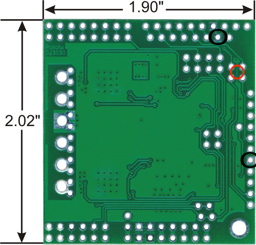
Fortunately, it looks like you severed a redundant GND connection, so you are probably fine not attempting a repair. You can test this by doing a continuity test between the points circled in black in the following picture. If you do not have continuity between those points, you can solder a wire between them.