
Hello I Just purchases The Pololu Drv8825 and followed the diagram about how to set everything up but im still not able to get an output or step out of my stepper motor. I have even put a multimeter across A A1 and got no reading whatsoever.
Im using a netduino to send the step pulse and using 12 v power supply .
If anybody could shed some knowledge to help me out that’ll be great.
Hello. I am sorry you are having trouble with the DRV8825 carrier. Could you please provide more information about what you are doing? What motor and power supply are you using? How did you set the current limit? You soldered the header pins to the carrier, right? What code are you running on the netduino? What connections have you made exactly? A picture showing all your connections and your soldering would help. Also, we have a couple different versions of the DRV8825 carrier, so could you please provide a link to the product page of the one that you have?
–David
Well I don’t have the circuit wired up anymore but here’s a diagram.
The motor I’m using : sparkfun.com/products/10847
The Pulse is a simple on and off signal every 50ms from pin 5 on my Netduino Plus 2.
Im not sure about the current limit but I tried turning it to multiple positions and testing the motor outputs and still got nothing.
I did not solder but I have used the multimeter to check for continuity on every pin to make sure contact to breadboard was good.
Lastly I’m using the MD20A version of the DRV8825

You will need to solder the header pins into the carrier to ensure good connections.
You should connect the DIR line to GND or 3.3V to ensure that it is not floating.
Also, I noticed that you were connecting the FAULT output pin to the 3.3V regulator from your Arduino. That is OK because we have a resistor protecting that pin, but that connection is not helpful so I recommend removing it. Generally, outputs should not be connected together.
The current limit is explained on the product page:
pololu.com/catalog/product/2132
I recommend reading the product page carefully to make sure you aren’t missing anything else.
–David
So should I leave the fault pin floating or use a pull up resistor because I read in the product detail that it should be connected to a pull up resistor to drive it high
You should just leave the FAULT pin disconnected. I am sorry if our documentation was confusing to you. Where in the product page did you read that a pull-up resistor is necessary? Could you quote the sentence?
–David
The DRV8825 also features a FAULT output that drives low whenever the H-bridge FETs are disabled as the result of over-current protection or thermal shutdown. Otherwise, the pin is floating, so you will need to use a pull-up resistor to give it a default high state if you want to use this pin. Note that there is a 1.5k protection resistor in series with the pin that you should take into account when selecting your pull-up resistor (i.e. it should probably be at least 10k). This 1.5k series resistor means it is safe to connect this pin to a logic high voltage, as might happen if you use this board in a system designed for the pin-compatible A4988 carrier.
I guess I misunderstood this section but I’ll leave it floating and try again later today
That’s for clearing things up I’ll post my results later
still a no go 
Hello. I am sorry it is still a no go. If you want help troubleshooting, please tell me all the details about your current setup. What are your current connections? What code are you using? We are not very familiar with the Netduino, so please make an extra effort to simplify it to the simplest possible thing that should work but does not. Please post some in-focus pictures of your setup using the “Upload Attachment” tab when you are writing your response, so we can see check your connections and solder joints. Have you used a multimeter to verify that each input to the driver is getting the voltage you would expect? How did you set the current limit? What brand/model is your power supply and how much current can it provide?
–David
OKay so I have soldered the pins and took some pics of everything I still get nothing no output voltage arcoss A A1 or B B1
I have attached the pics via pdf link
The netduino basically provides the step pulses on for (3.3v)500 ms and 0ff for (0v) 500 ms as measured.
The direction sleep and reset is connected to the netduino 3.3 v logic supply
The Drv8825 is gnd using the netduino gnd pin
I put a 100uF capacitor across vmot and gnd + side on the vmot pin and - on gnd and then the power leads comes from my converted atx power supply providing 12v. I’s capable of handles the required current needed for the stepper motor
I have used a multimeter to check voltages and connections and everything is good no shorts on the solder job although it may look so in the pics
The current limit was adjusted up and down didn’t get anything
If someone can post a pic of there setup that would be helpful
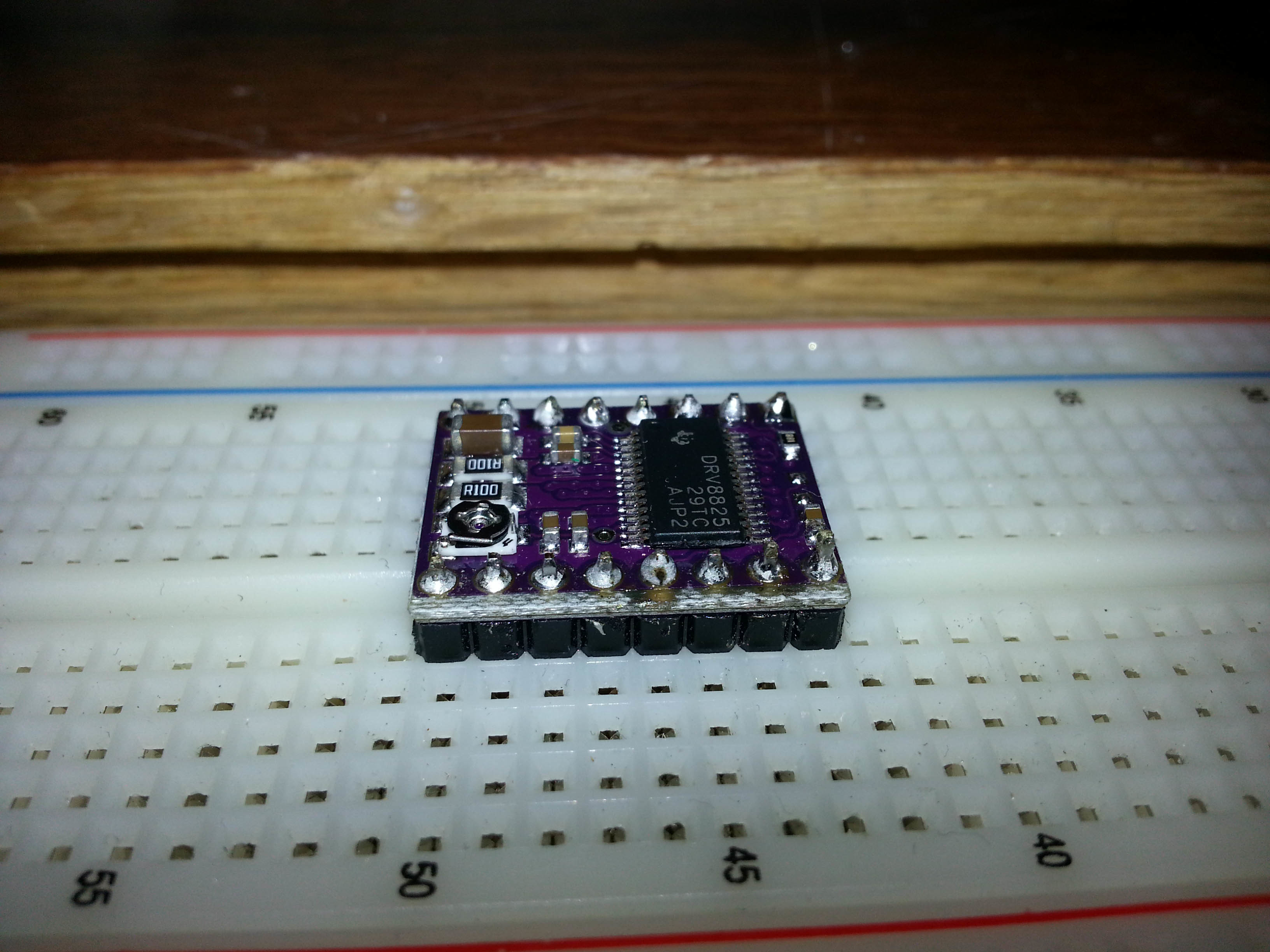
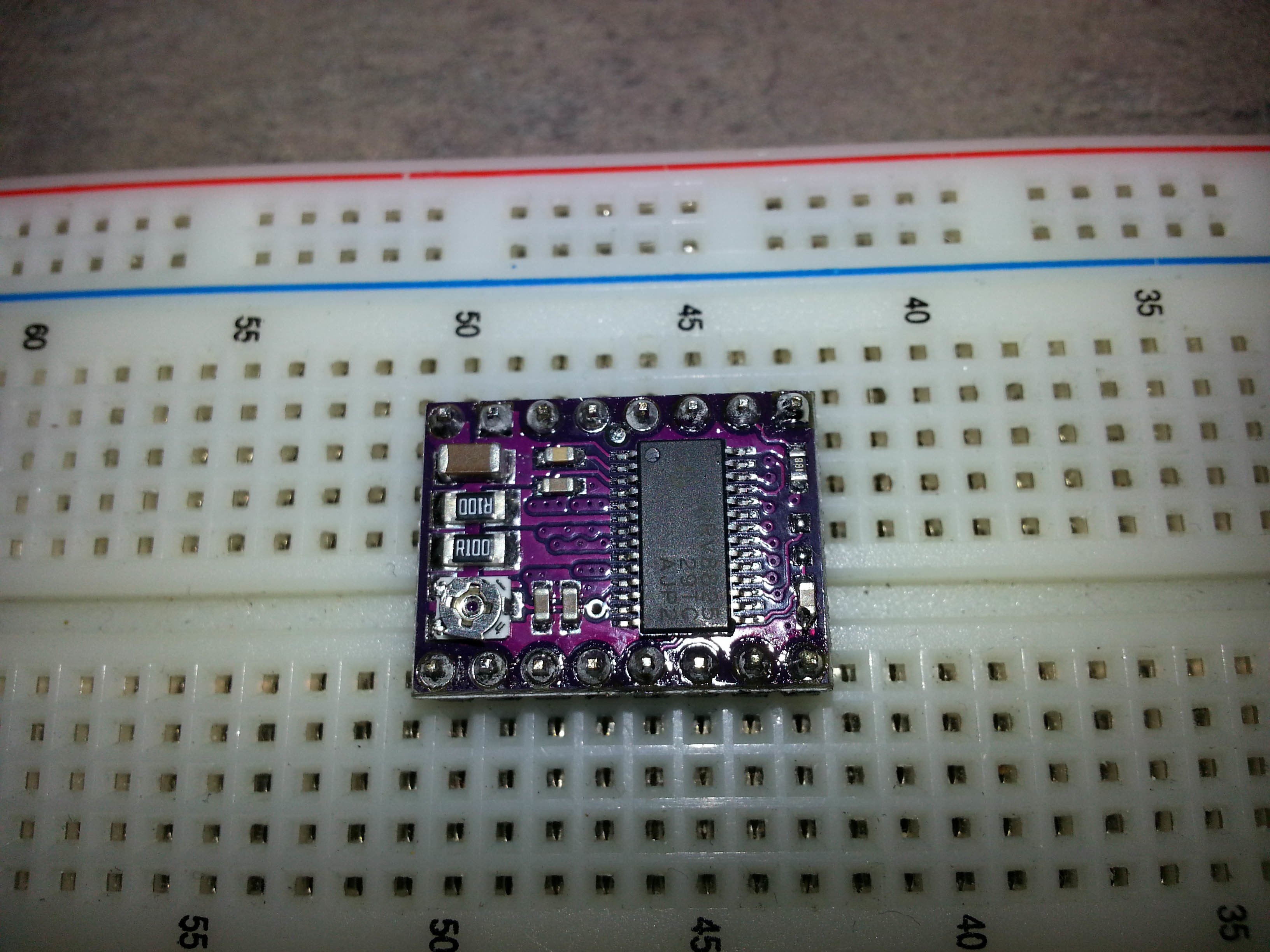
Hello. Thank you for posting those pictures. I think this one tells me everything I need to know:

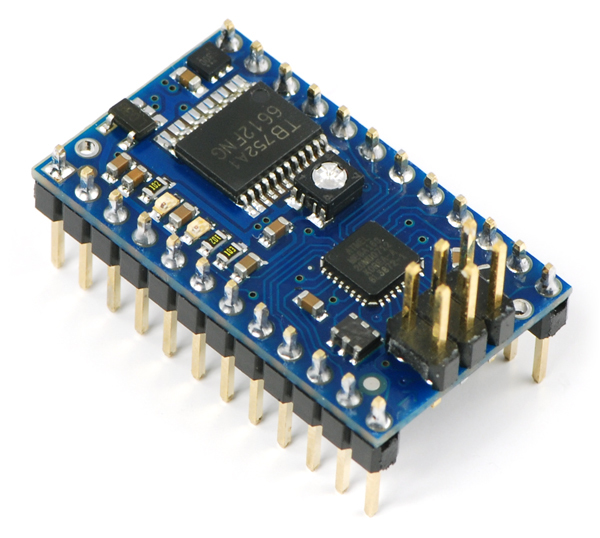
Most of those joints are not making a good connection between the pin and the pad. The point is that the solder needs to connect the metal pin to the metal plating of the through-hole, and it should flow down into the hole. You should make your solder joints look more like the ones in the photos on our website. This photo shows a different product with some good solder joints:
I recommend reading this:
ladyada.net/learn/soldering/thm.html
–David

Ye I thought so but I was using some thick solder that wouldn’t melt or blobbed up so I went out and bought some thin ones .
I got everything working but ran into problems.
IN the green zone of the picture attached the stepper motor moves but not very good it makes a screeching sound and vibrates. (I got a full rotation but the resolution wasn’t to good)
In the yellow zone it vibrates move and stops moving very finely back and fourth
In the red zone it kicks out and stops everything I measures the voltage across the fault pin but got a low reading 0v.
I thing it has to do with the current limiting I tried moving it back and fourth but didn’t get no better.
BTW I did this in 1/32 mode
Im going to try this at school using a pro power supply but my atx converted psu should be able to handle the 2 amps that this chip draws.
Also I would like to know which way rotating the current limiter will increase the current and decrease.
I got it working using PWM code I programmed using the netduino
I am glad you were able to get it working. To answer your question, rotating the potentiometer clockwise should increase the current limit.
–David
Alright thanks and also what’s the max step frequency that the DRV can handle
If I recall correctly, the maximum step rate the driver can handle is 250 kHz, but you should check the datasheet to confirm. However, you are almost certainly going to be limited by your stepper motor rather than the driver.
–David