I am using a Teensy 2.0, a Pololu drv8835 carrier board and two little gear motors from Pololu to build a small robot. I attach the code that I am using. Whenever I tell on of the motors.setMxSpeed commands to use a negative value, all is fine. However, when I tell it to use a positive value (like motors.setM1Speed(400)) the motor doesn’t turn. For example, my f() (forward) function works (actually backwards) with both motors turning but the b() (backward) function does nothing. Could anyone help me here? The code that I attach probably has some testing artifacts.
/*
 * altobot01
 * begun 12/12/2018 last modified 12/28/2018
 *
 * This code is designed to operate the altobot robot (Altoid
 * can) using a Teensy 2.0, a drv8835 motor ontrol board,
 * and two Pololu gear motors with an infrared receiver and
 * an Adafruit clicker. The code is based on the Pololu
 * drv 8835 demo code and the whegs03a1 code that I wrote
 * for another small robot that used a Trinket and two
 * continuous rotation servos.
 *
 */

#include <DRV8835MotorShield.h>
#include <IRLib.h>

#define MY_PROTOCOL NEC
#define LEDpin 11
#define BUTTON_0 0xfd30cf
#define BUTTON_1 0xfd08f7
#define BUTTON_2 0xfd8877
#define BUTTON_3 0xfd48b7
#define BUTTON_4 0xfd28d7
#define BUTTON_5 0xfda857
#define BUTTON_6 0xfd6897
#define BUTTON_7 0xfd18e7
#define BUTTON_8 0xfd9867
#define BUTTON_9 0xfd58a7

DRV8835MotorShield motors;

IRrecv My_Receiver(13);//Receive on pin 13
IRdecode My_Decoder;
long Previous; // Stores previous code to handle NEC repeat codes

void setup() {
pinMode(LEDpin,OUTPUT);
// uncomment one or both of the following lines if your motors' directions need to be flipped
//  motors.flipM1(true);
//  motors.flipM2(false);
My_Receiver.enableIRIn(); // Start the receiver
}

void loop() {
//  {

  if (My_Receiver.GetResults(&My_Decoder)) {
    My_Decoder.decode();
  if(My_Decoder.decode_type==MY_PROTOCOL) {
    if(My_Decoder.value==0xFFFFFFFF)
      My_Decoder.value=Previous;

switch(My_Decoder.value) {
//case BUTTON_0:  break;
case BUTTON_1: FlT();  break;
case BUTTON_2: f();    break;
case BUTTON_3: FrT();  break;
case BUTTON_4: lT();   break;
case BUTTON_5: stop(); break;
case BUTTON_6: rT();   break;
case BUTTON_7: BlT();  break;
case BUTTON_8: b();    break;
case BUTTON_9: BrT();  break;
}

  Previous = My_Decoder.value;
  }
    My_Receiver.resume();

  }
}
//
// M1 is the right motor
// M2 is the left motor
//
void f() {
  digitalWrite(LEDpin,HIGH);
//  int speed = 400;
  for (int i = 0; i < 10; i++) {
    motors.setM1Speed(-400);
    motors.setM2Speed(-400);
//
// using setSpeeds, only the negative speed works
//
//    motors.setSpeeds(400,-400);
    delay(2);
  }
    digitalWrite(LEDpin,LOW);
//    delay(500);
}

void b() {
  digitalWrite(LEDpin,HIGH);
//  int speed = 0;
  for (int i = 0; i <= 10; i++) {
    //
    // if I use two positive values here
    // the motors will not turn
    //
    motors.setM1Speed(400);
    motors.setM2Speed(400);
    delay(2);
    digitalWrite(LEDpin,LOW);
  }
}

void rT() {
digitalWrite(LEDpin,HIGH);
  for (int i = 0; i < 10; i++) {
    motors.setM1Speed(-400);
    motors.setM2Speed(0);
    delay(2);
  }
  digitalWrite(LEDpin,LOW);
}

void lT() {
  digitalWrite(LEDpin,HIGH);
  int speed = 400;
  for (int i = 0; i < 10; i++) {
    motors.setM1Speed(0);
    motors.setM2Speed(-400);
    delay(2);
  }
  digitalWrite(LEDpin,LOW);
}

//
// The FxT() and BxT() functions are actually slower versions
// of the regulard turn functions with directional commands
// thrown in.
//

void BrT() {
  digitalWrite(LEDpin,HIGH);
//  int speed = 400;
  for (int i = 0; i < 10; i++) {
    motors.setM2Speed(-100);
    delay(2);
  }
  digitalWrite(LEDpin,LOW);
}

 void BlT()  {
  digitalWrite(LEDpin,HIGH);
//  int speed = 400;
  for (int i = 0; i < 10; i++) {
    motors.setM1Speed(-100);
    motors.setM2Speed(0);
    delay(2);
  }
  digitalWrite(LEDpin,LOW);
}

void FrT() {
  digitalWrite(LEDpin,HIGH);
//  int speed = 400;
  for (int i = 0; i < 10; i++) {
    motors.setM2Speed( -200);
    delay(2);
  }
  digitalWrite(LEDpin,LOW);
}

void FlT() {
  digitalWrite(LEDpin,HIGH);
//  int speed = 400;
  for (int i = 0; i < 10; i++) {
    motors.setM1Speed(-200);
    delay(2);
  }
  digitalWrite(LEDpin,LOW);
}

void stop() {
  motors.setM1Speed(0);
  motors.setM2Speed(0);
  delay(2);
}
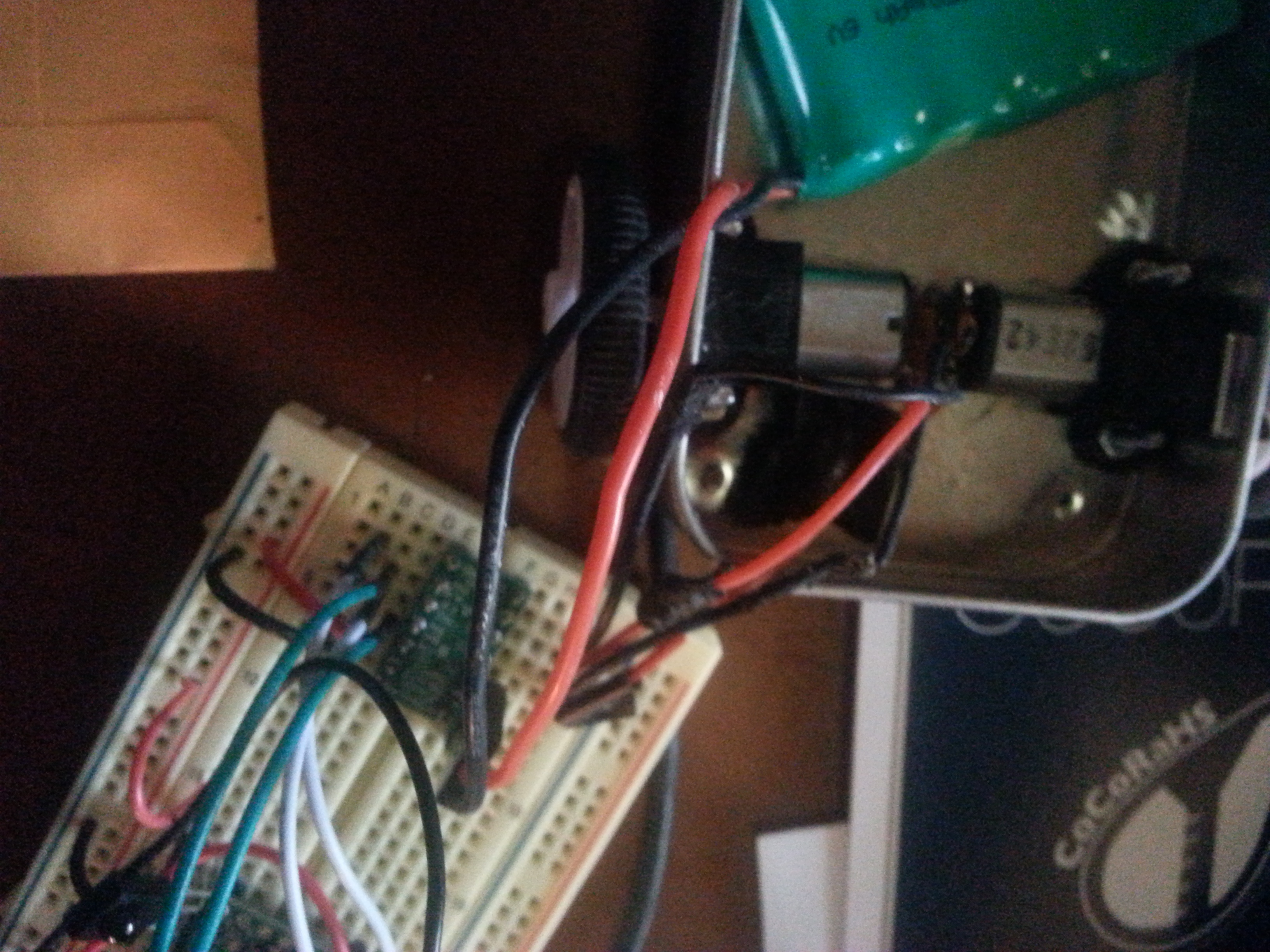
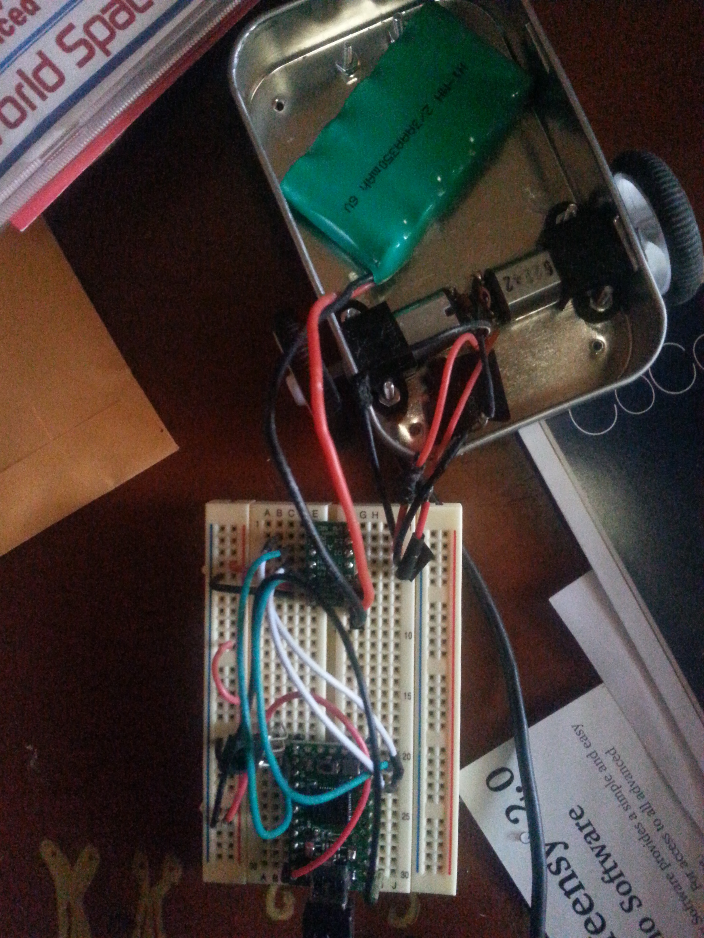
Do you get the same behavior if you run the demo sketch of the DRV8835 Arduino library? Can you post pictures clearly showing how everything is connected in your setup and close-up pictures of your soldering on the DRV8835 board and both motors?
If the demo sketch worked fine for your setup, then there’s probably something wrong with your code or IR transmitter. Your b() function looks fine. Can you verify that BUTTON_8 on your IR transmitter is actually sending the signal you are expecting (0xfd9867)?
Yes, it is doing that. There is a sketch in the irLib called irRecvDump which can tell you what codes your clicker is sending. I ran that on the breadboarded circuit in the picture and got the ir code that is in the Arduino code. Furthermore, you may notice the statements turning the LED pin on and off (on a Teensy 2.0, this is pin 11). The LED flashes when I click the button.
Motors can draw large amounts of current when switching directions and starting up. Can you try changing your speed values in b() to 100 instead of 400 and see if your motors are able to run at a lower duty cycle?
Before I do anything, I’ve been thinking (usually dangerous and ill advised). In the Demo .cpp file, the pinouts (as I recall) were the UNO SPI pins. Is the drv8355 board intended to communicate with the microprocessor via SPI or is this just a random pin assignment? If the communication is meant to be via SPI, the SPI pins on a Teensy 2.0 are different from those on an UNO (SS - 0, SCK = 1, MOSI = 2, and MISO = 3). I would have to switch the wires around to get this arrangement. None of these pins is mentioned as being a PWM pin. If I should use the SPI pins, please send me a pinout of which pins go to which pins on the carrier board. If this is not the case, never mind.
I looked at your connections and noticed the MODE pin (labeled MD) on your DRV8835 board is not connected, so your motor driver is operating in IN/IN mode and not PHASE/ENABLE mode, which is what the Arduino library for the Pololu DRV8835 (Dual Motor Driver Shield) is designed for. (The DRV8835 Dual Motor Driver Shield is pulled HIGH on the board, so it operates in PHASE/ENABLE mode. You can see this in the “Schematic diagram” section on the DRV8835 shield’s product page.) Can you pull the MODE pin HIGH and see if that changes anything? If connecting the MODE pin does not solve the issue, can you post a video showing your Teensy running the demo code (unmodified) so that I can see how the sketch is “working” in your setup?
Also, it looks like your connections to the Teensy are not correct. By default, the DRV8835 library uses Arduino pins 7, 8, 9, and 10 (which are defined at the top of DRV8835MotorShield.cpp), and according to the Teensy pinout diagram those pins are all located on the right-side of the board (as shown in your picture). However, in your picture it looks like three wires go from the driver to the right side of the Teensy and one wire goes to the other side. Can you post picture(s) that distinctly shows the connections between the motor driver and your Teensy board or post a wiring diagram?
The pin outs have been changed in the .cpp file. I had to change pin 10 to pin 12 in order to avoid a conflict with irLib. To what pin do I connect the MODE pin on the carrier board?
To set the driver in PHASE/ENABLE mode, you need to set the MODE pin high by connecting it directly to VCC or any I/O line on your microcontroller that is driving high.
I’ve tried setting MODE high with a jumper to Vcc and also (separately) by jumpering from pin 5 to MODE, creating a MODEpin in software and setting it HIGH with digitalWrite() in the setup section. Neither worked. Interestingly, jumpering from Vcc to MODE prevented the other movement functions from working at all.
It is not quite clear if what you are seeing from the motors is the expected behavior or not. Can you post a video showing how your motors are behaving when running your code versus the example code?
What values did you change the default pins in the DRV8835MotorShield.cpp file to? Can you post pictures that distinctly shows the connections between the motor driver and your Teensy board or post a wiring diagram?
I ran the demo again, this time commenting out the negative speed code. One motor turned; the other did not. I tried my code (and restored all your original pin outs in the cpp file). I got the same behavior. The motors do NOT turn when given a positive speed; only a negative speed makes them turn. I have tried various combinations of code and wiring without success. One thing that does seem to make a difference: whether I wire and code in the MODE. If I do, NOTHING turns. I wrote a little piece of code which ran the motors in a loop using the functions that I had written but without the IR connections. I wanted to see if there was a conflict between the IR code and the motor code. I got the same performance. The motors did NOT work with positive values. I have another carrier board. Should I try substituting this new one?
As soon as I get to the new board (I have to solder the pins - probably Monday), I’ll substitute it for the one that is on the breadboard now. I don’t understand some of your questions. What part of “The motors don’t turn” don’t you understand? I have reset all of the pinouts to what they originally were in the cpp file. I originally thought that there would be a conflict with IRLib which uses a timer on 10, so I reset your pin 10 (in the cpp file) to pin 12. Yesterday, I moved the jumper back to pin 10 (and changed the pinout in the cpp file to 10 from 12). The conflict which I thought might have occurred did not occur. All the wiring is now as your original; I still can’t get any movement when using positive values. Haven’t from the beginning. That’s what prompted this series of posts. I have literally checked everything: changed the wiring of the motors (things are tight; I thought that maybe I had the wiring mixed up. Nope.). BTW, the MODE pin is acting funny, as I have previously mentioned. Connecting it via jumper and code actually prevents ANY motor from turning. What’s this all about?
I understand that your motors are not behaving as expected, however it is difficult to pinpoint what exactly is causing the issue without getting a clearer picture of your connections, how you have them defined in the DRV8835 library, and a video showing the behavior you are seeing. For example, in your second post, you said the Demo sketch worked for your setup (using your modified connections defined in DRV8835MotorShield.cpp file), but I am skeptical that the demo program worked properly since the MODE pin on your DRV8835 board was not pulled high, which is the condition DRV8835 library is designed to operate in.
Pin 12 on the Teensy is not a PWM pin, so if you changed pin 10, which is used to control to the M2PWM pin on the DRV8835 board, to pin 12 that would explain the weird behavior you were getting. I strongly suggest looking at the “Minimal wiring diagram for connecting a microcontroller to the DRV8835 dual motor driver carrier in phase-enable mode” picture under the “Using the motor driver” section on the DRV8835 carrier board’s product page and making sure that you have two PWM pins connected to the motor ENABLE pins and have them defined correctly in the library. Then run the demo code again.
Also, just to be sure that your motors are capable of rotating clockwise and counter-clockwise, can you connect each motor directly to your battery and see if they are able to rotate in both directions by switching the polarity (or swapping the power supply leads to the motor)?
In order to satisy my mind a bit, I set up one of your boards with an UNO and two “plastic” gear motors and exactly the same wiring as I had for the Teensy. I ran your test program. It worked as it was designed to work.
You asked whether the motors can change directions. I ask you, since I bought the gear motors from Pololu, they can.
According to PJRC (the manufacturer of the Teensy 2 - do not confuse it with a Teensy 3x) pin 12 IS a PWM pin.
Could the problem be that a Teensy 2 cannot generate the necessary signals? I’m going to go on the PJRC Forum to see if anyone else has had this problem.
You are right. Pin 12 on the Teensy 2.0 is a PWM pin. I was looking at a pinout diagram of a Teensy 3.x version; sorry about that.
Our library tries to specifically use Timer1 (and reconfigure it for 20kHz PWM) on ATmega32U4 processors. The Timer1 PWM outputs OC1A and OC1B are on pins PB5 and PB6, which map to Arduino pins 9 and 10 on standard 32U4-based Arduinos (like the Leonardo and Micro, as well as our A-Star controllers). The Teensy 2.0 PWM pins also uses the ATmega32U4, but it looks like it maps those pins differently, to pins 14 and 15. Pins 10 and 12 are mapped to Timer4 on the Teensy 2.0 according to the table under the PWM Frequency section on the “Pulsed Output: PWM & Tone” page on the PJRC’s website. Can you try using pins 14 and 15 for PWM, or comment out line 5 in DRV8835MotorShield.h to make the library fall back to using analogWrite(), which should work on any PWM pin? Also, please make sure that the MODE pin is pulled high.
Using the wrong PWM pins in combination with the MODE pin not being pulled high would explain the behavior you are getting. With IN/IN mode (the MODE pin is disconnected or pulled low), the Teensy is controlling the DIR pins but not driving the right PWM pins, so your motors only rotate in one direction. With PH/EN mode, since the Teensy is not driving the right PWM pins, you are seeing no movement from either of your motors.