I’m having trouble figuring out where I’m going wrong with the G2 motor driver. I’ve used these before and as far as I can tell, I’m using it the same as I did before. What I’m seeing is the drive current jumping rather than ramping with the PWM input.
Here are some more details of my setup:
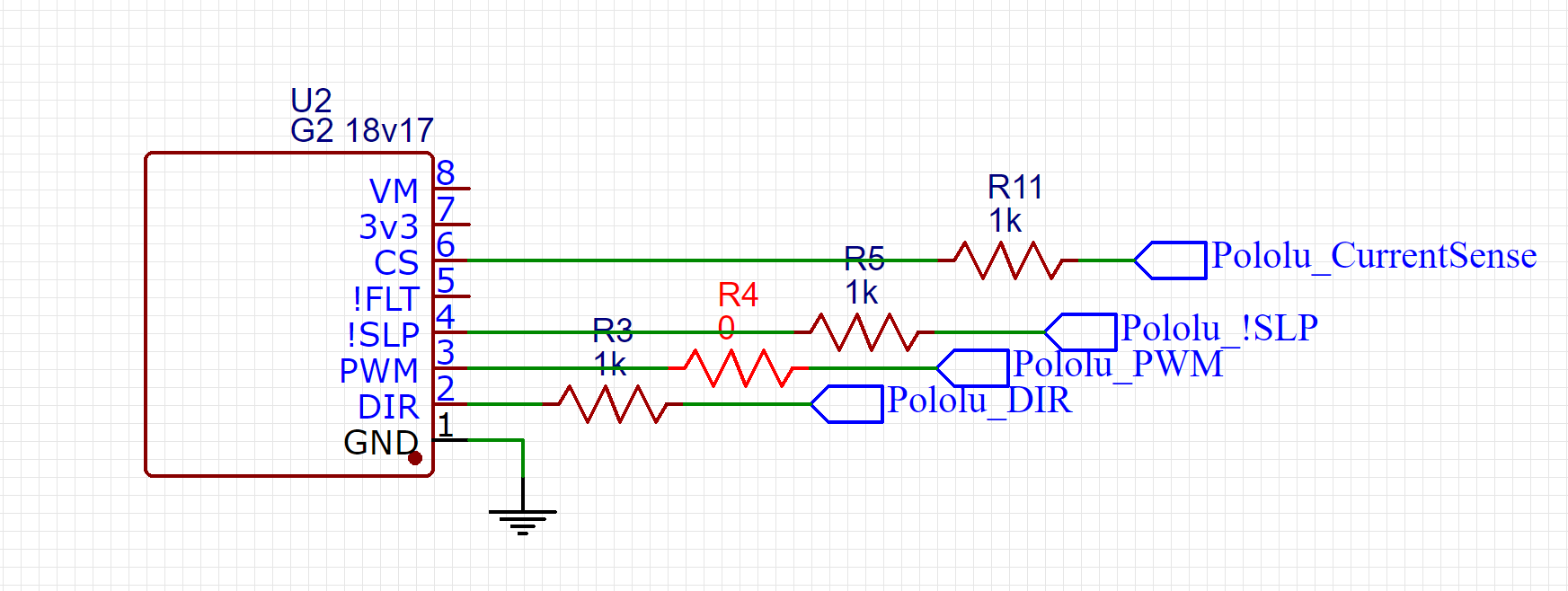
Arduino PWM to G2 PWM (100 resistor between)
Arduino digital pin to G2 DIR (1k resistor between) pulled high
Arduino digital pin to G2 !SLP (1k resistor between) pulled high
I’ve scoped the PWM output and sure enough it ramps fine. I can set the PWM to 50% and that seems fine, but it won’t ramp up from there.
When you say it will not ramp up from there do you mean that your Arduino is not outputting a higher duty cycle PWM signal or that the motor speed does not get faster after increasing the duty cycle? What are you using to provide power to your motor driver? Can you send pictures that clearly show your current setup and connections?
The PWM signal continues to increase in duty cycle, but the motor speed does not increase to match.
Here’s a video of what’s going on:
What you are seeing on the screen is the PWM value being called for by the Arduino. The actual PWM signal going to the driver is on the scope. What you see is that I start the PWM signal at 50 (out of 255). I use that to detect that the pressure switch has been activated and the motor needs to turn on by watching the current sense pin. I’m not running the detection code in this example, but explaining why it starts on slightly. From there, I ramp up the PWM signal by 1 every 5ms until 255. The motor doesn’t speed up, but when it hits full duty cycle the motor tries to spin up immediately and saturates the current limit on the power supply.
I tried another controller and the same thing happens. I have a 500uF cap installed on one and nothing on the other.
I just installed a current limiting resistor to limit to ~10A. The motor comes on fine when it peaks out, but I’m still not able to ramp to full speed.
Thanks for the video. What Arduino are you using? Can you post pictures that clearly show your current setup and connections? Are you powering your Arduino from the same supply? If not, make sure your Arduino and driver have a common ground. Can you tell me the specs of the motor you are using and if there is any load on it?
Everything is running from the same power supply. Grounds are common.
The motor is a 24VDC compressor. ~3A running. It currently has nothing connected to the outlet, but the motor itself still has to drive the compressor elements so there is a small load.
I noticed that the board you are using has a maximum input voltage of 15V; are you running it at 24V or are you running your motor at a lower voltage? Are you measuring the speed in some way or is it just by sight? Can you try running your motor at a lower duty cycle and then jump to a higher one to see if there is a difference?
There is power regulation on the PCB. The motor runs on 24V, the arduino on 12V. Aside from ramping up the power, there is no speed control on the motor. I’ve been using the PWM for current regulation rather than speed control. The test you are describing is essentially what is happening now.
I start the PWM at 50, then ramp it to 255 (over about 200ms). The result is the motor starts at 50 and then jumps to 255 and goes overcurrent.
I’ve resorted to just putting a current limiting resistor on the driver and running the PWM at 255 all the time. That works well enough for now. Is there a cheaper offering than these drivers that does the same thing without PWM control? Maybe I’ll just switch to them.
I’m not sure what you mean by “using the PWM for current regulation rather than speed control”; can you explain what you mean in more detail? Do you have your motor directly connected to the output of the G2 motor driver? If you probe the driver outputs together with the PWM signal you are sending from your Arduino to the driver, do their duty cycles match?
I’m not interested in speed control of the motor. I only bought this part for preventing the inrush current from saturating my power supply’s over current protection.
The motor is directly connected to the G2 and the G2 is directly connected to the power supply via dedicated lines. I’ll try checking the duty cycles on the G2 output side.