I am having trouble getting a stable reading from the current feedback on my 24V13 G2 motor driver. I have tried both hardware and software filters to no avail. I am using a Python based processor. Any ideas?
I would like to monitor the steady state current to shutdown the driver when it exceeds my desired limits. So the filter doesn’t have to be fast. Simple is better.
Can you provide more details about your setup (e.g. connections)? What microcontroller and motors are you using with the G2 High-Power Motor Driver 24v13? Can you post links to their specifications or product pages? What hardware and software filters have you tried? Also, what frequency and duty cycle are you running your PWM at?
Hi Amanda - My application is driving small brushed DC motors in model trains, 12-24V, 0-100% duty cycle, at 20KHZ. Processor is the Atmega128FRA1.
I tried simple R/C filters, with values all over the map. Nothing helped. In software I tried taking the average of a number of readings over a period of time (a couple of seconds). No help.
What resistor and capacitor values did you use in your RC filter? If you have not done so already, can you try using an RC filter with a cutoff frequency between 500Hz and 1000Hz and see if that helps? Also, do you have access to an oscilloscope that you could use to look at the CS output?
Hi Amanda - I’ve had this project sidelined for awhile. Today, I discovered I no longer have any motor output from my G2, so I guess I’ll have to buy another one. Any warranty on these? I had no problem driving it previously. I have verified a good PWM signal in, 0V out.
I am sorry to hear your driver is no longer working. Due to the sensitive nature of our products, we do not offer blanket warranties, but we stand by our products and work with customers to try resolve any problems. Since your G2 driver was initially working, it seems likely either something damaged the board or something in your system changed, and we should try to figure out what happened before you try again with a new unit. Did anything change in your setup between when it was working and now? Can you post pictures of your current setup clearly showing how you have everything connected?
Thanks Amanda. I have another on order. I thought it was still working when I left the project awhile back, but maybe it wasn’t. I had been doing load testing on it, pushing it to its limits, so I may have damaged it. Perhaps that is why the current reading was so bad as well. I’ll try again with the new one. Thanks for your help. I’ll let you know how it goes.
Hi Amanda - I received my second G2 and gave it a try in the same setup. It seems the direction input is not working, even though I am able to toggle the DIR pin between 0 and 3.3V, I always have the same polarity on the motor output.
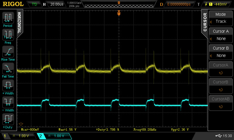
And the Current Sense output is the same as the other one. I thought it should be a DC output proportional to current. But it is a PWM signal, same frequency as the PWM input (20KHZ). Simple RC filters do nothing but change the slope of the PWM edges.
The attached photo: top yellow signal is filtered with a 20K/10uf filter. bottom blue trace is CS output with a 1.0 amp load.
I added a 220uf cap across the + and - holes. A 47K is installed across VRef.
So two questions: 1) It appears my new board is defective. Can I get a replacement? 2) How do I make the CS output useful?
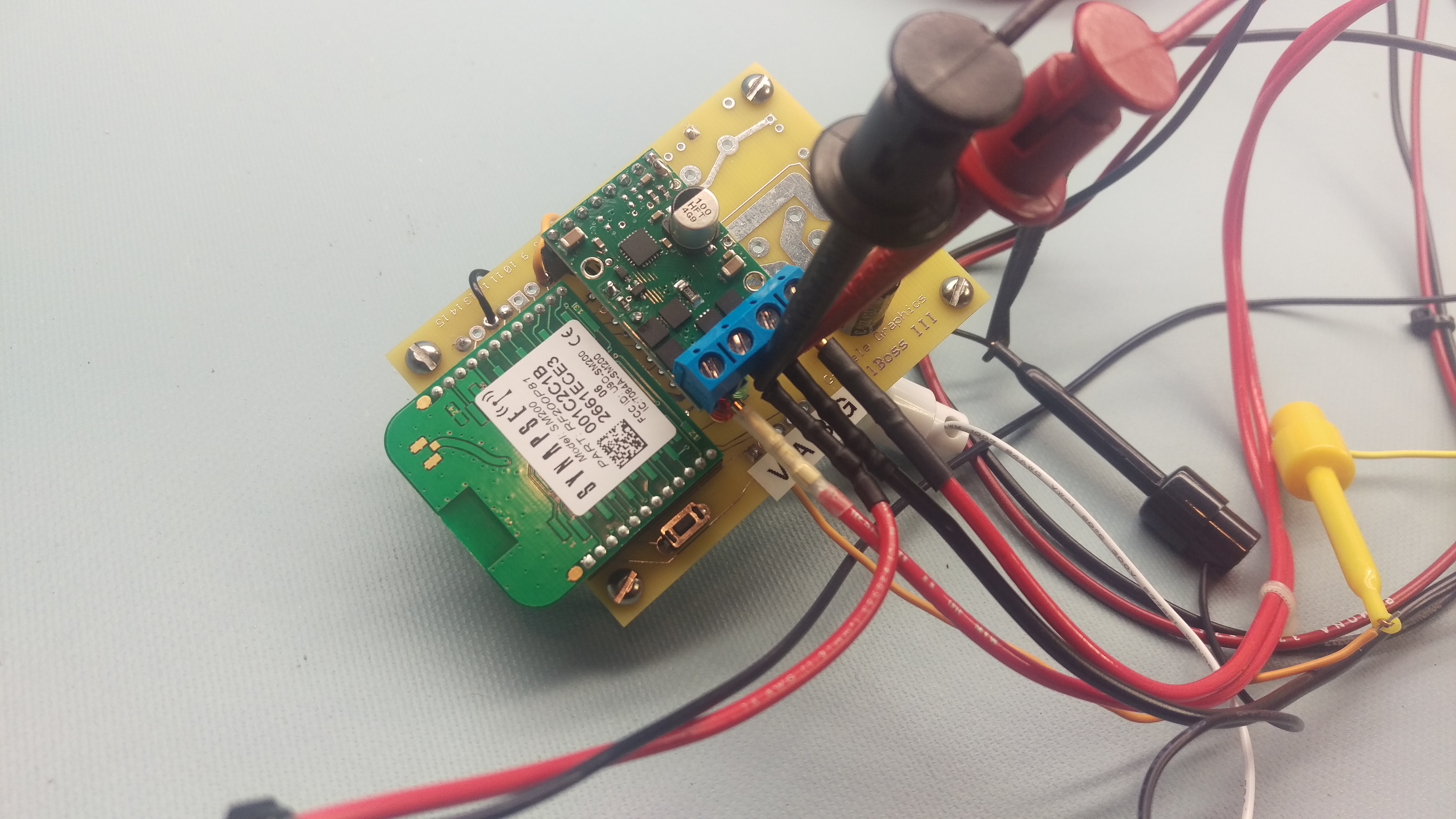
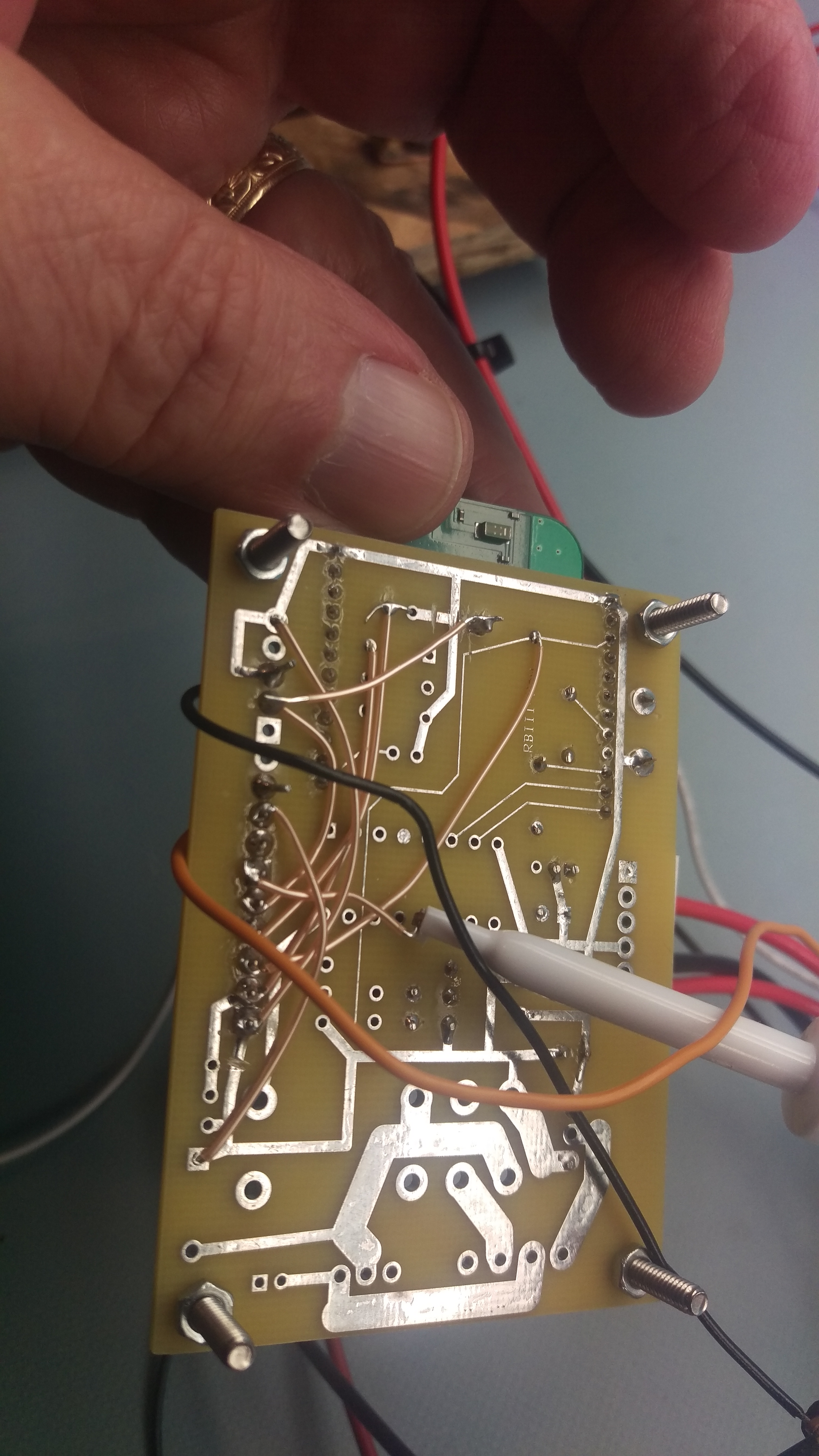
We test every unit, and given this is now the second unit you are having trouble with, I think we should look more carefully at your setup. Can you post pictures of your setup showing all of your connections clearly and both sides of the new G2 board?
As for your second question about the current sense output, as we say on the product page, that pin outputs a voltage proportional to the motor current only while the H-bridge is driving, so you only get a meaningful reading during the active portion of your duty cycle. One way to use it is to average the signal with an appropriate RC filter or in software and divide that average by the duty cycle to get the current through the motor. Your scope capture makes it look like your RC time constant is maybe 1 us, not the 200 ms you would get from 20k and 10 uF, so your capacitor or resistor value is probably not what you think it is.
Also, 1 A should give you only about 90 mV and your pulses are much bigger than this, so something in your setup is probably not what you think it is.
Hi Amanda - I am trying to incorporate this unit into my own product line. I have been an electrical engineer in test engineering for over 40 years. I also do my own customer support for my products. So I understand you want to insure I have the proper connections. However, the time and effort to take photos that you still couldn’t trace the wires and PCB hacks, is not possible. I’ve attached some anyway.
As to the Direction not working. I can toggle the direction pin 0 to 3.3V measured AT the pins of the G2, while measuring the voltage on the G2 outputs, and the polarity does not change. So it is the board, not the setup/connections. And anyway, this same setup with the first board did work just fine. It wasn’t working the first time I fired it up. I really don’t think I could have zapped anything.
The reason my filter wasn’t working? Common connection on by breadboard slipped off! So that makes sense. I can now smooth the CS output good enough to get some readings. I just have incredible amounts of noise (spikes from the PWM switch) that I will need to deal with.
I am glad that you resolved your original problem with getting stable readings from the CS pin on the G2 board.
Nowadays, with everyone having great cameras in their phones, it is easy to post a few pictures, so we think requesting those is a very low bar, and seeing what you’re doing can be especially valuable, both in terms of quickly identifying problems and assessing how well engineered your setup is. And even if you do have lots of experience, you have seen first hand that it’s easy to make simple mistakes like leaving a ground wire disconnected, so it’s good to have a second set of eyes look things over.
We understand situations like this can be frustrating and do appreciate your patience. Since it looks like there is a lot going on in your system, can you remove the G2 board from everything, including your motors, and measure the output voltage while toggling the DIR pin directly?
By the way, did you test the new G2 board before connecting it to your system?