
Hello
I’m trying to run a simple DC motor with G2 High-Power Motor Driver 18v25 using PWM from the arduino to control the motor speed.
I want to use the whole range 0-255 for one direction only, and change the direction using the DIR pin (LOW / HIGH for CW /CCW) that on the Motor driver.
In my setup:
when the ‘pwm’ value is 0-126 the motor turn to one direction
when the ‘pwm’ value is 128-255 the motor turn to the other direction
when the ‘pwm’ value is 127 the motor is at break state and there is a terribly noise from it.
I wm reading a vlaue from a potentiometer and than setting this value ad PWM signal for the motor.
in the process i’m printing the 'pwm value on the screen just to see it
The wiring that i did is:
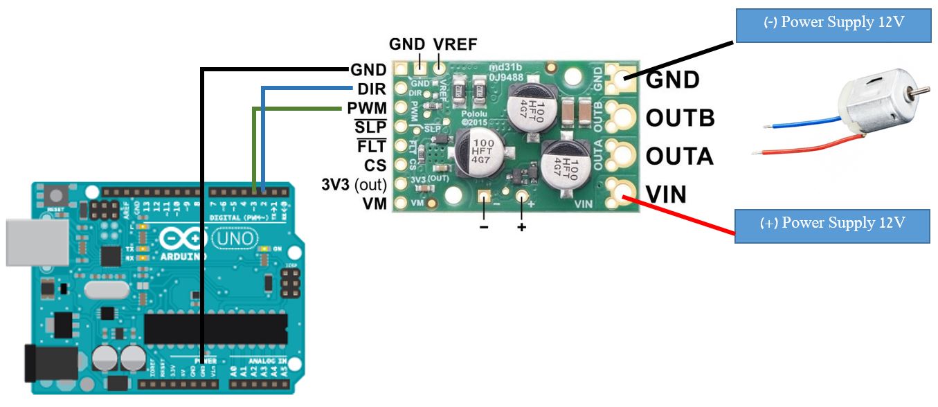
Motor Driver        |          arduino
GND                 |          GND
DIR                 |          2 (Digital Pin)
PWM                 |          3 (Digital Pin- PWM~)
The arduino code is very simple:
#define DIR 2
#define PWM_motor 3
#define pot A0

int pot_read = 0, pwm = 0;
void setup() {
  Serial.begin(9600);
  pinMode(PWM_motor, OUTPUT);
  pinMode(DIR, OUTPUT);
  pinMode(pot, INPUT);
}

void loop() {
  digitalWrite(DIR,HIGH);
  pot_read = analogRead(pot);
  pwm = map(pot_read, 0, 1023, 0, 255);
  Serial.println(pwm);
  analogWrite(PWM_motor, pwm); // Send PWM signal
  delay(10);
}
Can you please explain me what i did wring, or how properly use your motor driver
thank you for the help.