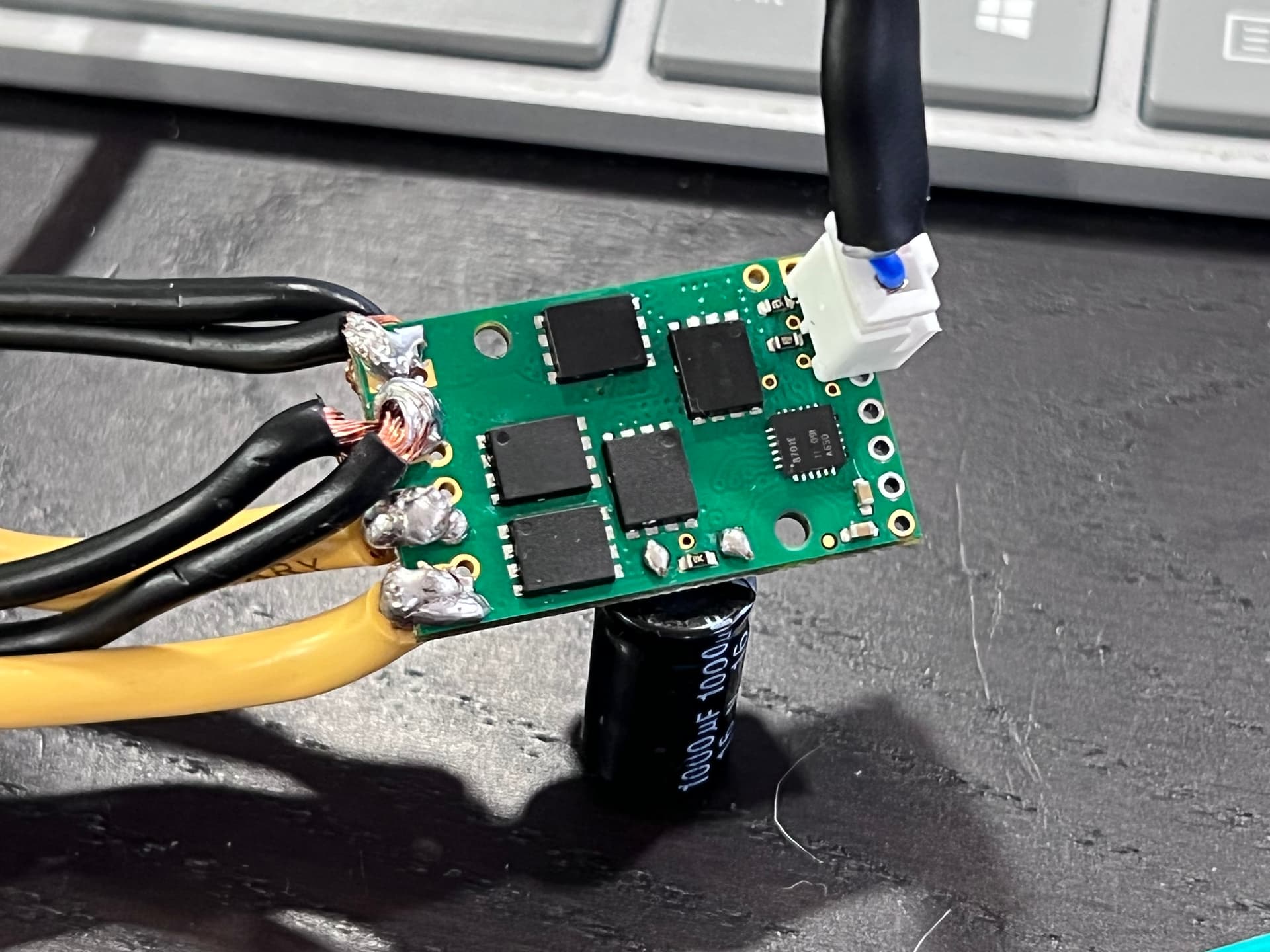
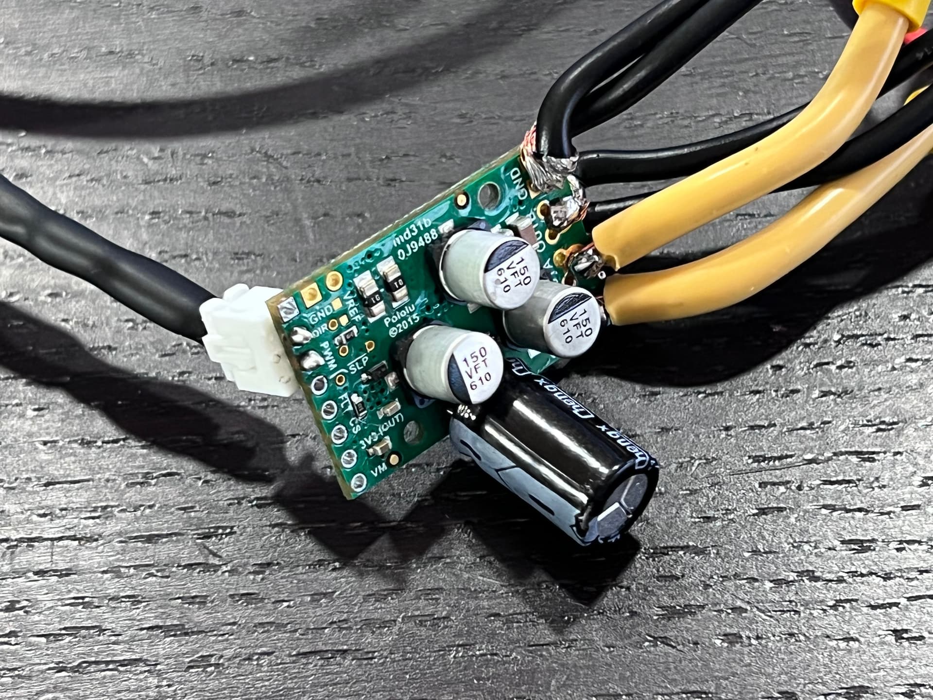
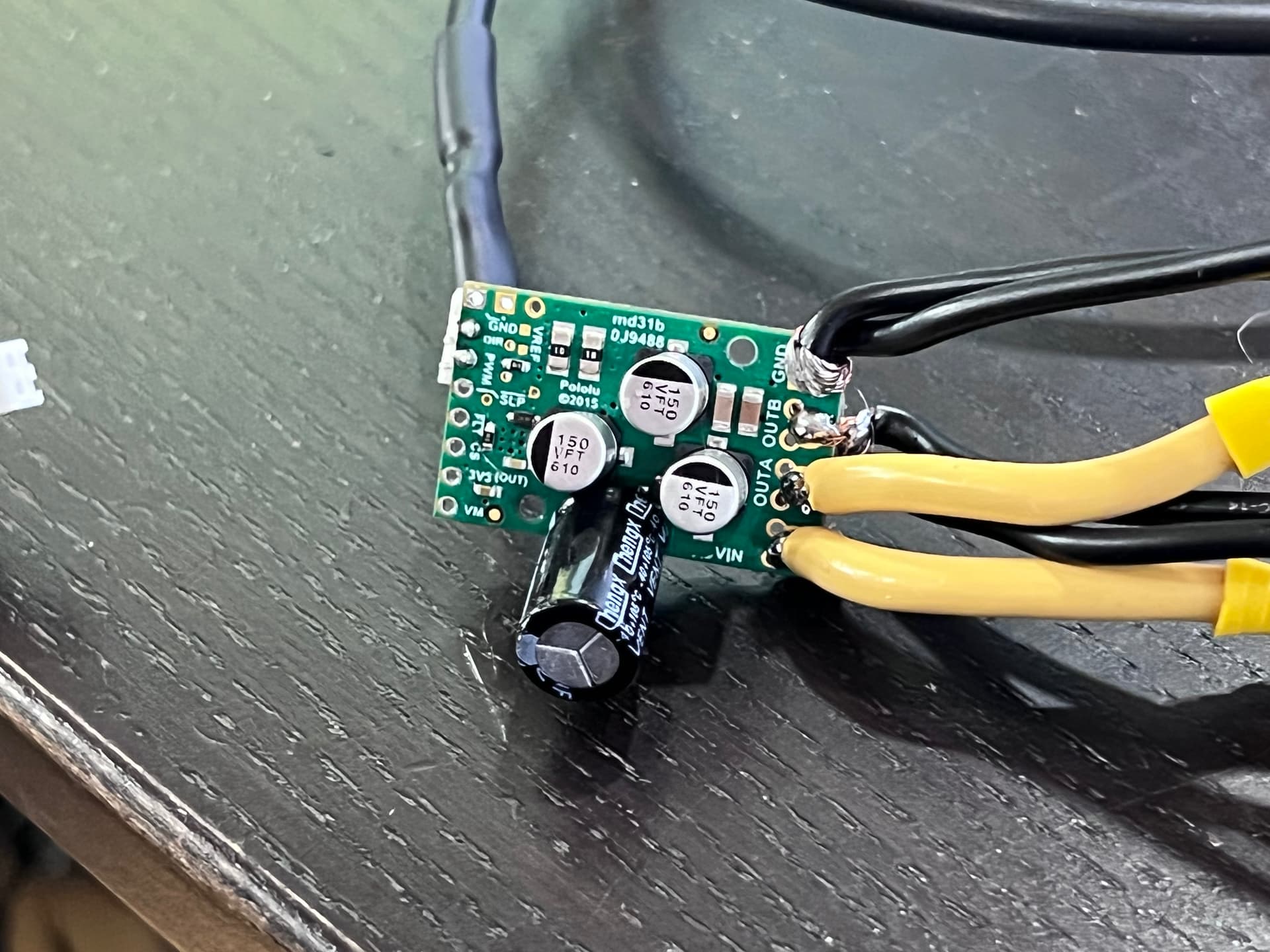
I am using a G2 18v24 to drive a 12v 20A car blower motor driven by an Arduino Mega. I have installed a 1000 uF capacitor as per the instructions. I’m holding the DIR pin high at 5v and using the PWM pin to vary the speed. I’m using 10 gauge wires, because that’s what was originally connected to the blower motor. These really don’t fit in the holes on the board, so the soldering is a bit of a mess, but it seems fine.
I bench tested with a small 12v motor and it worked fine. I hooked up the blower motor in the car being powered from it’s 12v battery and it also worked, but with a loud ~490 Hz tone due to the default PWM frequency of the Arduino (presumably).
I made some small changes: I replaced the jumper wires and headers with a proper JST-XH connector and a cable, updated the PWM frequency of the Arduino to remove the tone, that kind of thing I tested it on the bench with the small motor and it worked.
I moved it to the car and got nothing – the motor doesn’t turn, and the output pin reads as ground. I then tried the small motor again and got nothing. I reverted the Arduino code and it still doesn’t work. I put everything back on the bench with the bench power supply and it doesn’t work with either motor. I verified continuity on my JST-XH connectors and cables, so the fault isn’t there.
When I do not connect a 12v power supply to the board, I see 5v at DIR and 5v (when set to 100% duty cycle) on the PWM pin. But once I hook up the power supply and motor, I only see 0.06v (at 100% duty cycle) on the PWM pin.
The FLT line is floating (I’m not using it and don’t have the pull-up installed, but it reads 1.0v with a multimeter; I assume it’s pulled to ground on a fault, not just “less than 2v” or something like that). The 3.3v pin reads 3.3v, so I’m guessing the voltage regulator seems good.
This suggests to me that something on the board has failed or shorted on the PWM part of the board. It’s not clear to me what I did to kill it, or if it’s possible to fix it.
Unfortunately, either way, it does sound like your driver was probably damaged. If the PWM signal from your Arduino is getting pulled down, that indicates a short in the driver IC. Can you post some pictures of what your installation in the car looked like?
It is generally not practical to repair those drivers, but if you email us with your order information, we might be able to help you out with a discount on a replacement.
Yes, right, it’s the G2 High power Motor Driver 18v25.
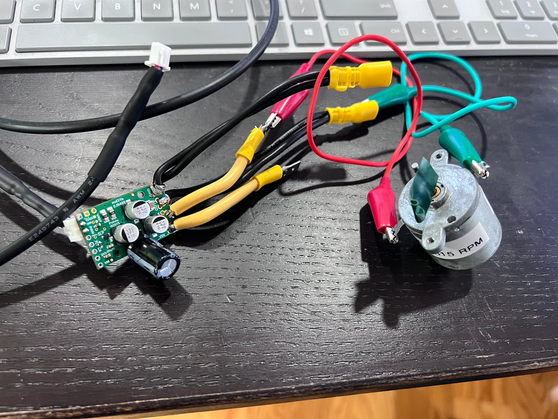
I’m afraid I don’t have any pictures of the driver installed in the car, but I do have it on my bench with a small 12v motor hooked up to it.
The wiring is:
10 gauge wire to VIN from the car battery
10 gauge wire to Out A and to the motor’s 12v input
Two 14 gauge wires to GND from the car battery
Two 14 gauge wires to Out B to the motor’s ground input on the case.
2-pin JST-XH connector soldered to the PWM and DIR pins. DIR is connected to 5v.
The 10 gauge wire is because that was used in the original circuit. It really doesn’t fit in the holes on the board, though, which led to some rather messy soldering. But it worked.
The pairs of 14 gauge wire is because I ran out of 10 gauge wire, so I doubled up on 14 gauge wire to get an effective 11 gauge cable. I intended to replace it with a proper 10 gauge wire once I got some.
I originally had the header pins installed on the board, but removed those for the JST connector. It did work on the bench with the JST connector installed, so I don’t think I damaged anything there. It was only when I put it in the car that things went wrong.
It’s difficult to judge how well you had your installation protected against inadvertent shorts; are you pretty sure you can rule those out? Were you trying this with the engine running, and did you have any protection against voltage transients on the 12V bus in your car?
I’m strongly leaning towards some kind of transient killing it. I currently have no protection in my circuits, but oddly haven’t had any issues until recently. I’ve had a project in the car for a few months, but I just recently killed a comparator input and latching relay board in it. I’ll be adding TVS protection when I make PCBs for my next version.
I don’t recall running the engine with the motor driver installed – I’d just turned on accessory/run power so I could test the blower – but that doesn’t mean a transient from something else didn’t kill it. For example, I had the car on a charger, so maybe a surge from that was the problem.
I know car electrical systems can output >60v spikes, so I wouldn’t be surprised if a spike on the VIN pin might have killed the driver (honestly, I’m surprised I made it this long without anything getting fried).
To reduce the chance of mixing up the wires, I used male connectors for 12v and female for ground. I also made sure that the 12v wires are different lengths than the ground wires to prevent them from short to each other, in addition to using sheathed spade connectors to reduce the chance of shorting further. Even so, it’s certainly possible that something shorted while I was fumbling around and getting it all hooked up. I’m going to switch to Deutsche connectors in the future to make it more fool-proof; the spade connectors were less than ideal.
I’m more of a programmer than an electrical engineer, so I’m still figuring this stuff out. I just need to learn what kind of protections to put in place to keep this from happening again.
I read through the application note and my takeaway bas basically “add a TVS across the motor driver VIN and GND pins”, and to do so as far away as possible from the components for best results. It seem like this would work, anyway, but it’s one of those things that seems hard to test without risking blowing up another driver. Easy enough to do, though.