I’m trying to drive a 12V DC motor with the G2 driver. Connected to the 3.3V output is a microprocessor sending PWM (calculated through PI control) back to the driver. I didn’t have any large capacitors on hand, so I’m only using 100uF.
I had the whole setup on the bench operating before I jammed it into a prototype of mine, after which I notice the fault pin is driven low, and all the pins appear to operate except for the output pins. I’m concerned it was my manhandling that led to my issue, but I’m not sure. I had gripped the board with pliers right between the output pins and I tugged on one of the pre-existing capacitors on the board while installing the board in a cramped spot. My soldering job also isn’t really anything to be proud of…
The weird thing is that my multimeter doesn’t see a short across the output pins, the board is getting full 12V input, and there’s no heat to speak of. Is the fault pin still activated because part of the board is dead? If the board is dead, what exactly killed it? I don’t want to repeat any errors.
Could you post close-up pictures of the soldering and components on the driver? Have you checked for continuity between your pull-up resistor on the fault pin and the pin itself on the board? What motor are you using?
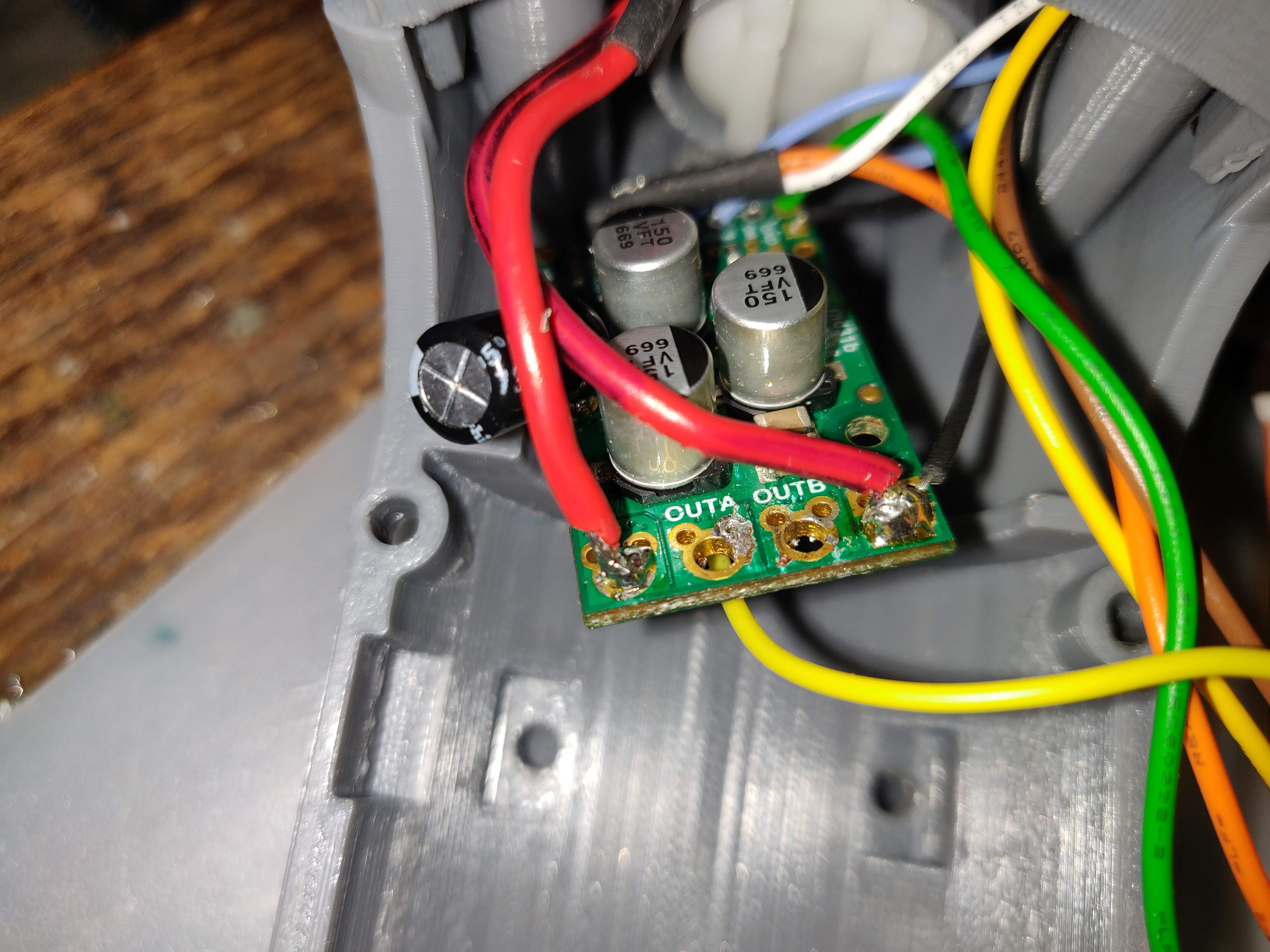
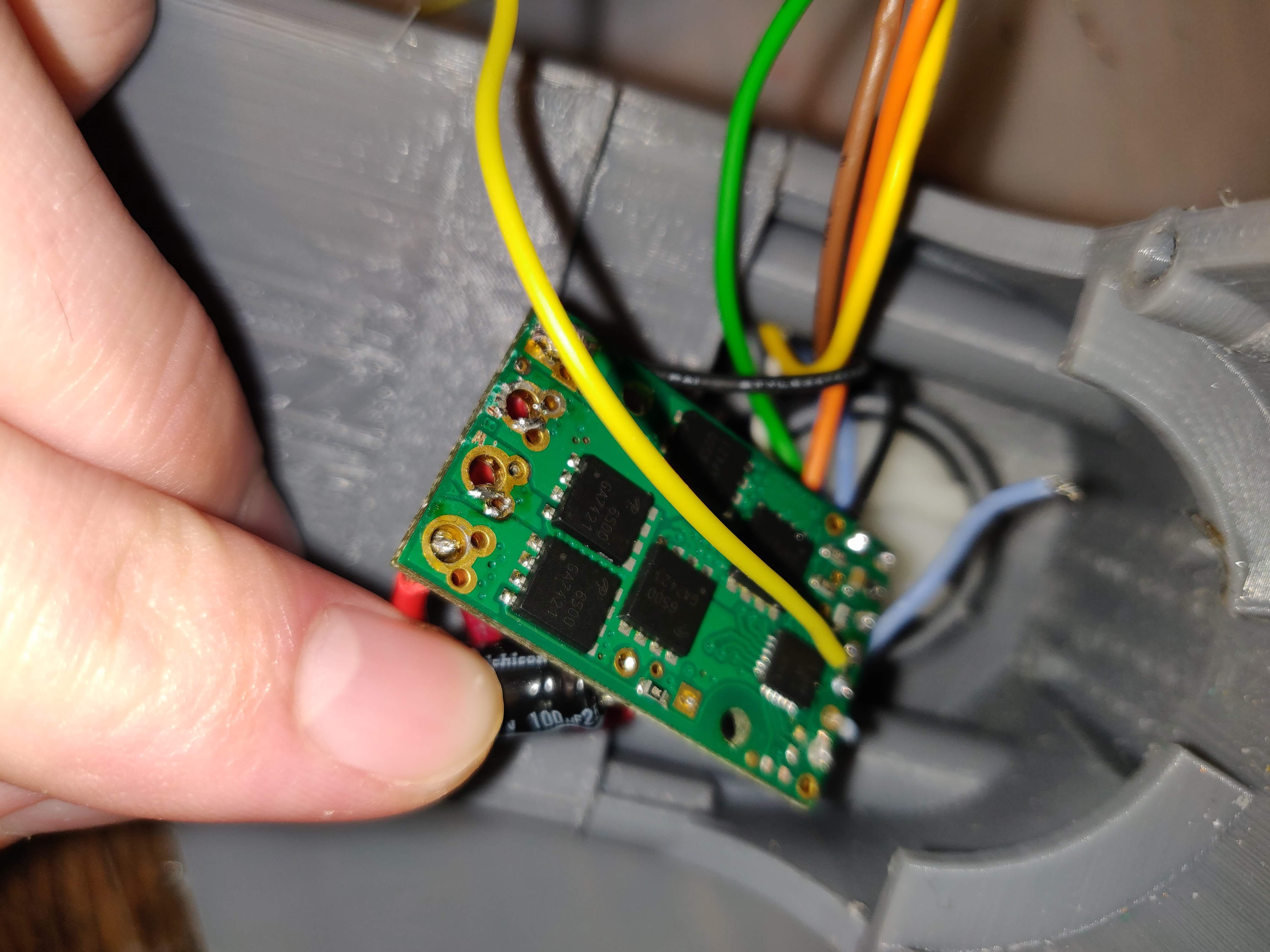
Here are a few pics of the board. Because of the way the board is sitting in the prototype, it’s tricky to get a good shot of the full board. I’ve removed the leads connecting to the output pin. Even with these leads gone, the board still registers a fault.
I used a built-in resistor in the teensy LC microprocessor, so there’s no continuity to check- I only used pinMode(x, INPUT_PULLUP).
The motor is a 12V, 20A max brushed DC motor from servocity with an encoder on the back. When hooked directly to 12V the motor spins. Like I said, the whole system was working on the bench before I tried to put it into the prototype.
Those solder joints are not the best, like you mentioned; how did you check to make sure that the board was actually getting 12V power? It looks like the driver is being mounted in a metal enclosure; did you take any precautions to make sure that none of the pins shorted against the case? Did the driver ever work after being transfered to your enclosure?
2 things make me think the driver is getting enough power- I read it with a multimeter (and it was ~12V) and the board is still sending 3.3V to the logic circuit.
The enclosure is actually PLA plastic, so I’d be surprised if that’s shorting anything. To prevent the enclosure from melting, the board is mounted via its mounting holes, and there’s a gap between the board and the enclosure.
The driver never worked once it was placed in the prototype. I redesigned the enclosure (to require less manhandling) and put in a new driver, and it’s working fine for now.
You are correct, if the low VIN fault was being triggered, the 3.3V output would be disabled. It is not clear to me what is damaged, but if your new unit is working, it seems very likely that the other is broken.