
I’m controlling a bipolar stepper motor using Maestro 12-Channel controller connected to a DRV8825 Stepper Motor Driver Carrier. The Maestro is being controlled by a VB6 application using a serial interface. When I send a series step commands the stepper motor moves in one direction for a few pulses and then it moves opposite direction for a few pulses. I’m sending chr$(0) to set the driver low and then I’m sending a chr$(254) to set the driver high. I’m using a 2 millisecond delay after the set low command and after each step pulse. I know if I increase the delay the motor stops tuning. Anyone have any ideas?
Hello.
I am sorry you are having trouble with you project. Can you post some pictures of your setup and a wiring diagram? What is the current limit on your DRV8825 stepper motor driver carrier set to? Have you tested your setup using the Maestro Control Center? What are you using to supply power? Also, please post the VB code you are using.
-Derrill
I’m using a Pololu 9VDC Regulated Power Supply for the stepper motor, a 5VDC from the Maestro for logic power, 6VDC Regulated Power Supply for servo power and USB power for the Maestro Controller power. I tried to use the Maestro Control Center with the two channels I’m using for the stepper motor set to Output. However, nothing happened–the motor did not move. Now I’m not versed in the Maestro Control Center so is most likely something I’m not doing.
Attached are the pictures of the setup and the VB Code. I don’t have a wiring diagram. I’ll work on one tonight and put in another post.
Keep in mind that the VB6 code is from a commercial application I’m producing so there maybe some references to functions and/or procedures are missing.
StepperMotorProject.zip (346 KB)
I forgot to answer the current limit question. I attempted to use the reference voltage to set the current limit but could not get to work. No matter which direction I turned the pot the voltage never changed. The voltage jumped from 43 volts to 54 volts without doing anything. So I turned the pot to it’s lowest setting.
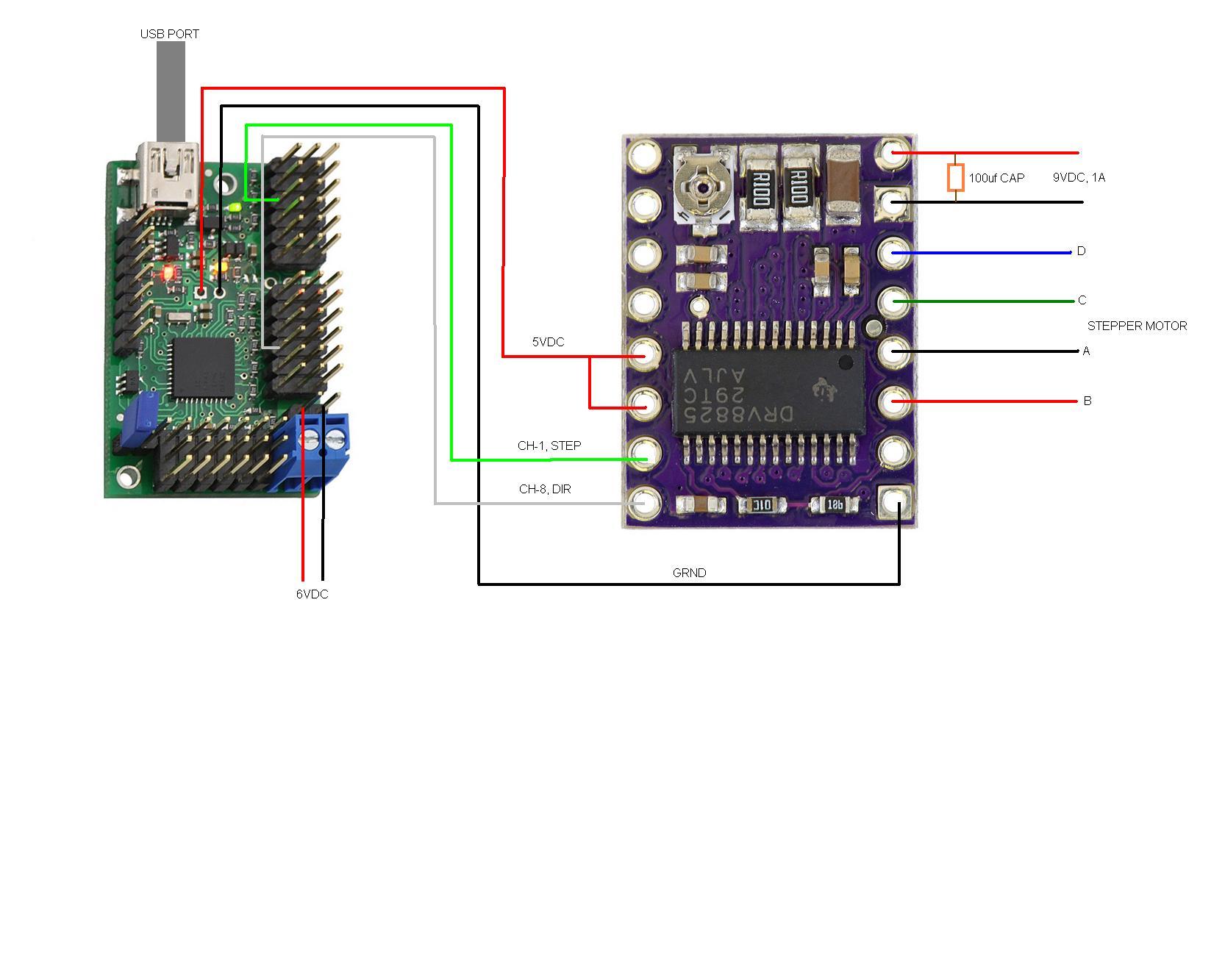
Attached is the project’s wiring diagram…
I tried setting the current limit again with my old volt/ohm meter (my new digital meter does not work for some reason). This time I saw values from .75 volts to 3 volts. Right now I have it set at 1 volt. However, I’m seeing the same behavior.

How The Software Works
The software was designed specifically for stop motion animation production to control a camera motion control system.
Each position is contained within an event. Each event can contain as many as seven components (Pan, Tilt, Dolly, Focus, Arm-Horizontal, Arm-Vertical and Rig). A position can be an integer between 1 and 254.
The stepper motor is going to drive the dolly (camera slider). The turn ratio between the slider and the stepper motor is 1:1. It takes 14 revolutions to move from one end of the slider track to the other end.
Here’s the sequence for moving the stepper motor:
- Position is passed to the Move Stepper function.
- The direction is determined by comparing the previous position with the new position. If the new position is greater than the previous position a zero (forward) is sent to the controller. If the new position is less than the previous position then a one (reverse) is sent to the controller. The direction controller channel is an offset of the step channel (i.e. Step Channel 2, Dir Channel 9)
- The number of pulses (steps) to be sent is determined by calculating the difference between the new position and the previous position. The result of the calculation is then multiplied by step factor so that stepper motor will always makes at least a quarter turn move.
- The pulses are sent using a For-Next Loop with a zero (Chr$(0)) sent to the controller to set the step to low followed by a 3 millisecond delay.
- A 254 (Chr$(254) is then sent to the controller to set the step to high followed by a 3 millisecond delay.
- Once the loop have executed a zero is sent to the controller to set the step low.
Here’s a link to a video of the stepper motor’s erratic behavior:

I figured out what was causing the problem. I noticed instructions for connecting the stepper motor to the driver did not match the DRV8825’s wiring diagram. Once I changed the motor connections to match the DRV8825’s wiring diagram the motor started working correctly. I also changed the the code for switching to the reverse direction from chr$(1) to chr$(254).
Man, all that for just a simple mistake in the instructions.
I am glad to hear you found the problem. Thank you for letting us know.
Can you tell me where the error in the instructions is? If we have instructions with an error, we certainly want to correct it.
-Derrill
The instructions were referring to connect a bipolar stepper motor to a A4983 or A4988 driver. I was not paying attention when I read the instruction and failed to noticed that it referred to two specific drivers. It was only when I was making the wiring diagram for you that I noticed that the DRV8825 driver wiring diagram did not match the instruction. It my fault. This kind of thing happens as I get older.
Thanks very much for your help. Your request for more information in what lead me to discover the cause. Now all I have to do is add micro switches at each end of the camera slider to prevent the stepper motor for damaging the slider if it end the end. Plus, I need to put rubber cushions between the stepper motor and the sliders driver system so the motor wont shake the camera to pieces.