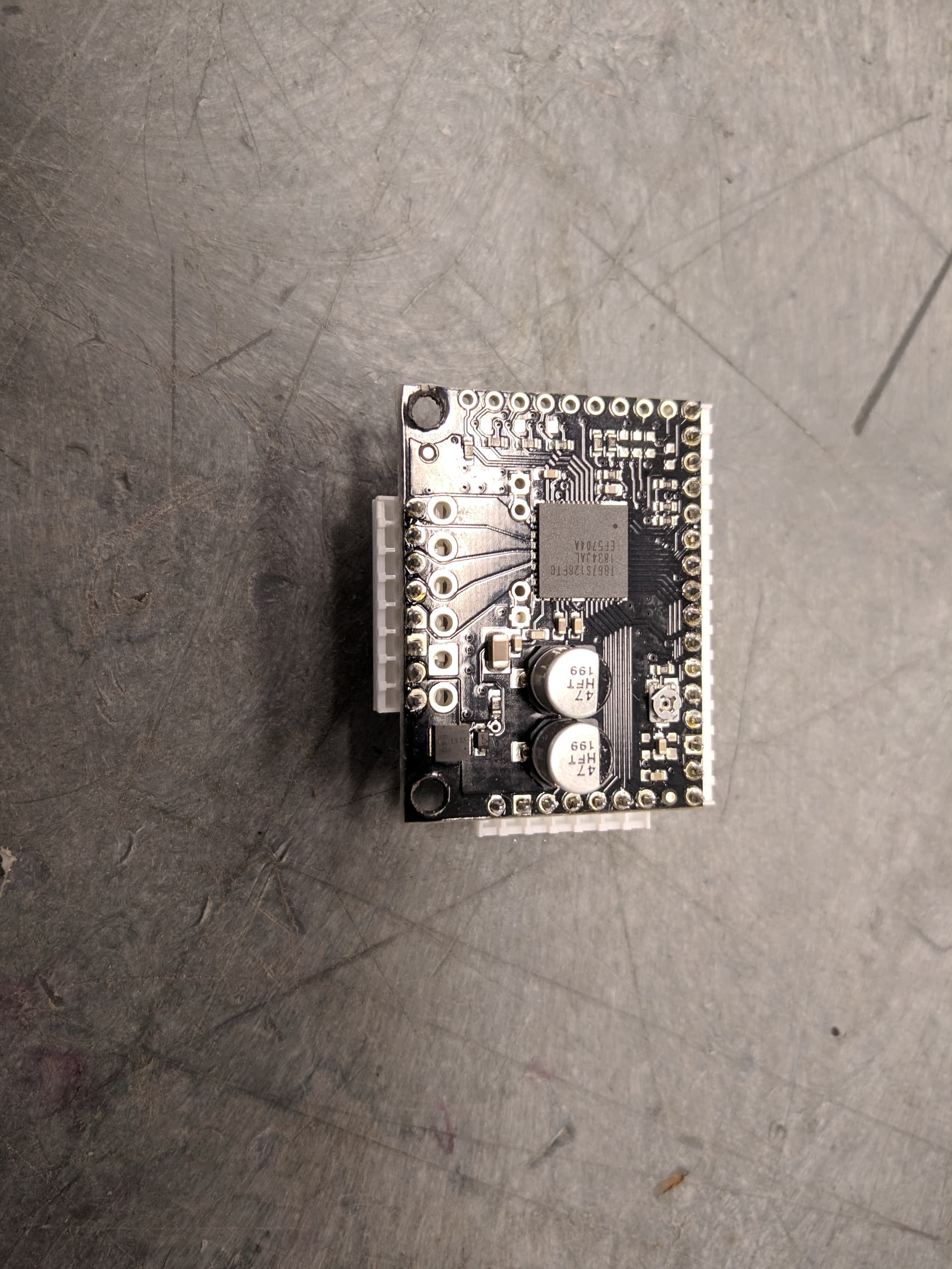
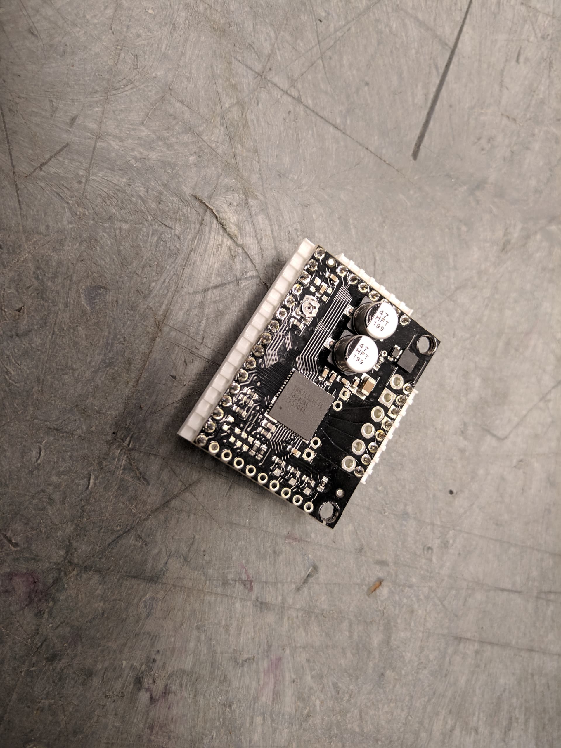
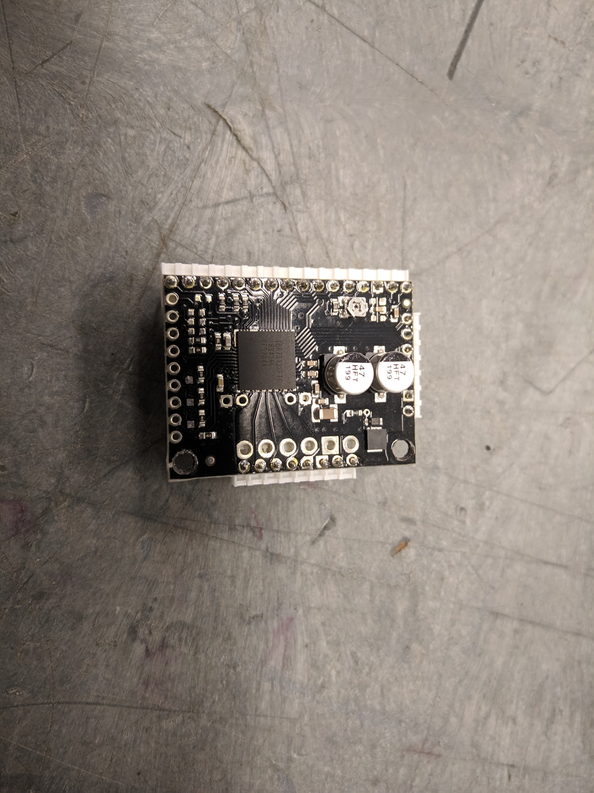
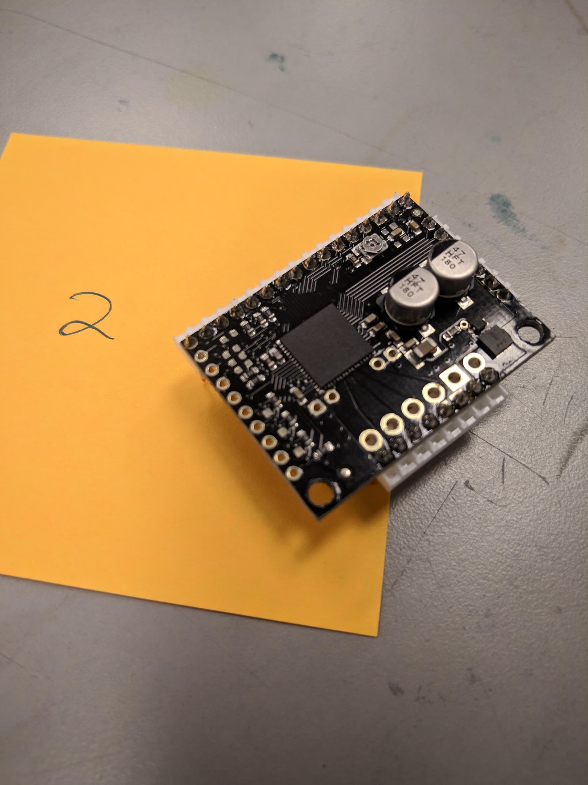
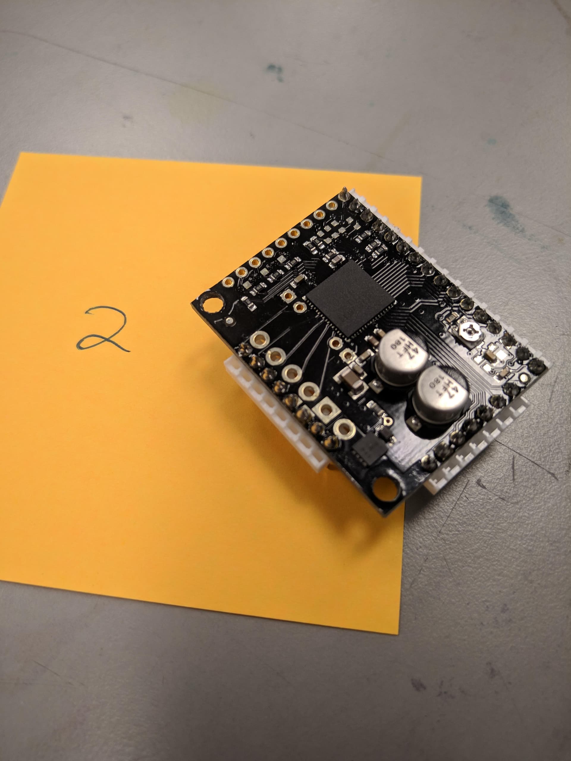
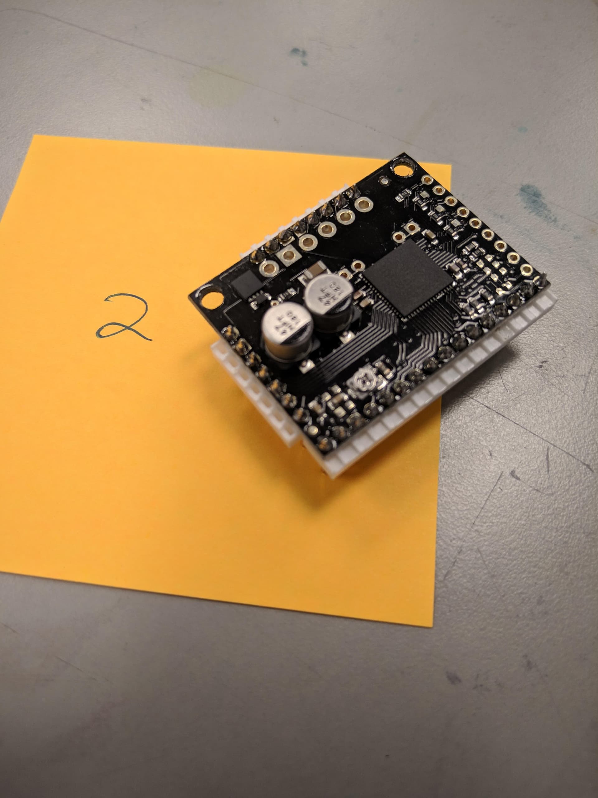
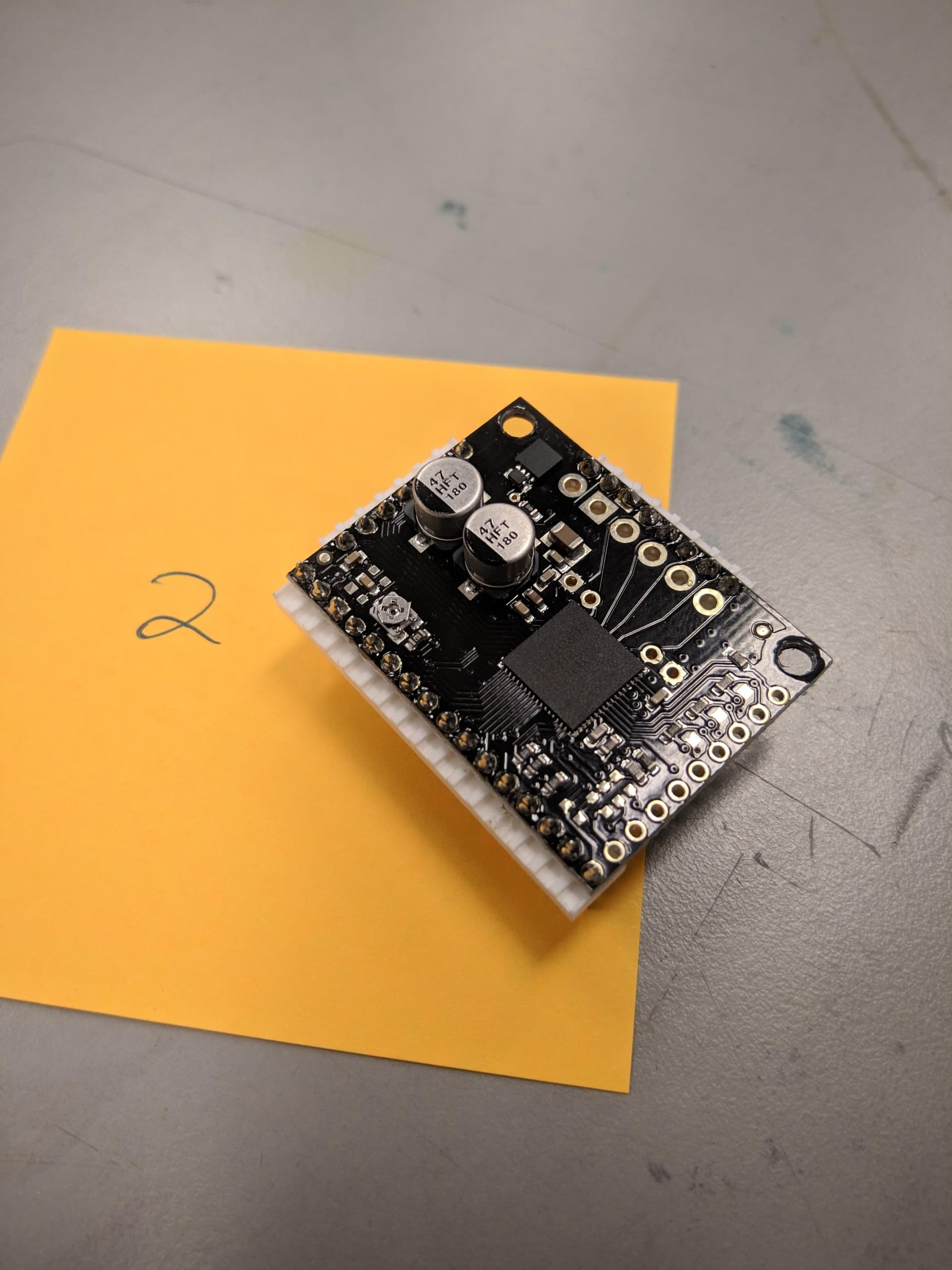
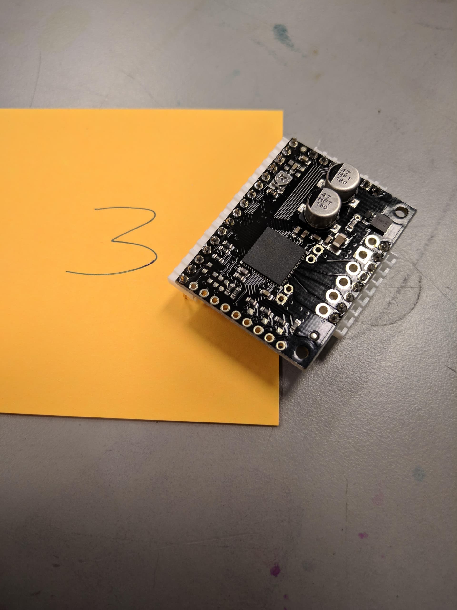
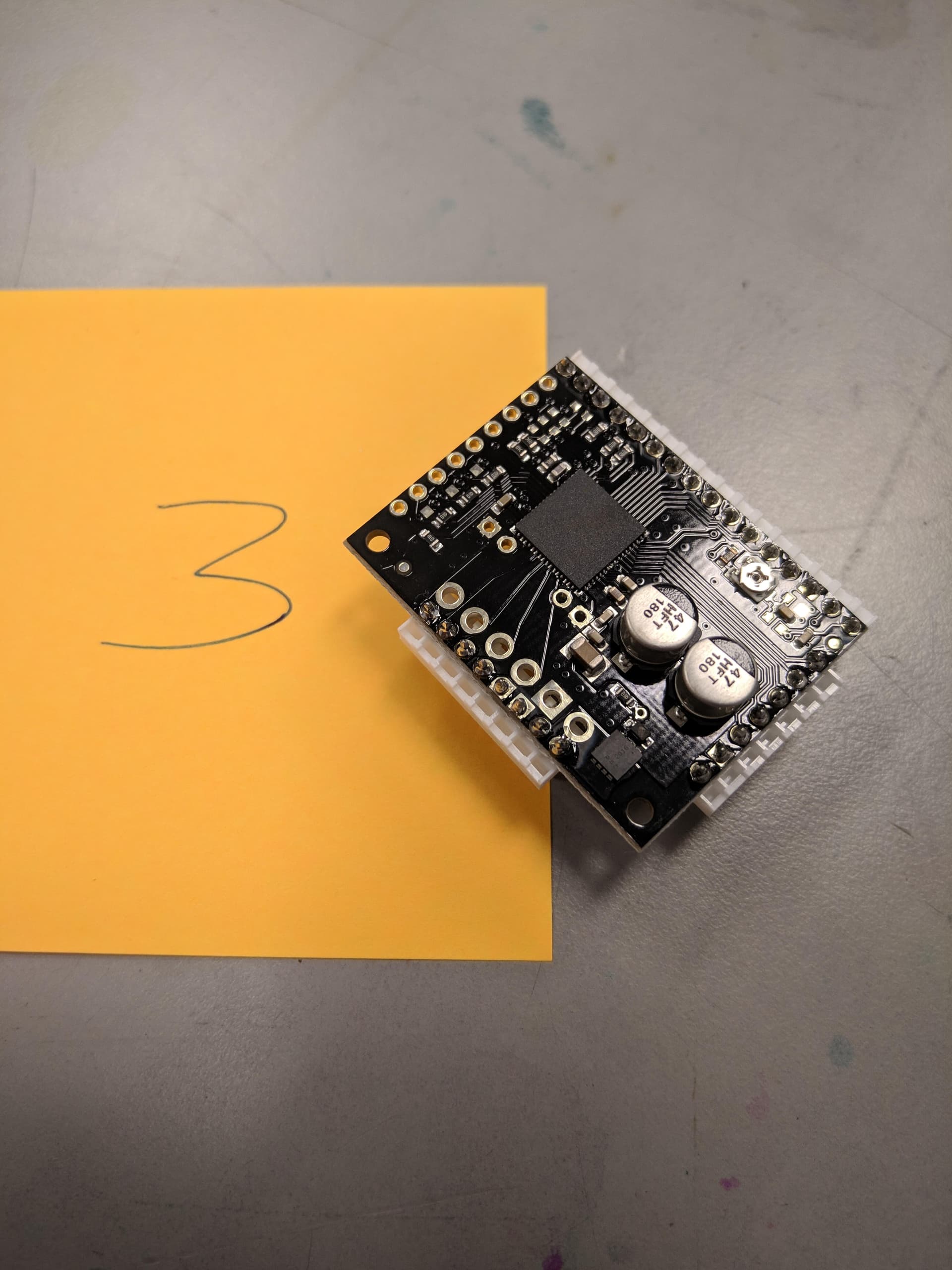
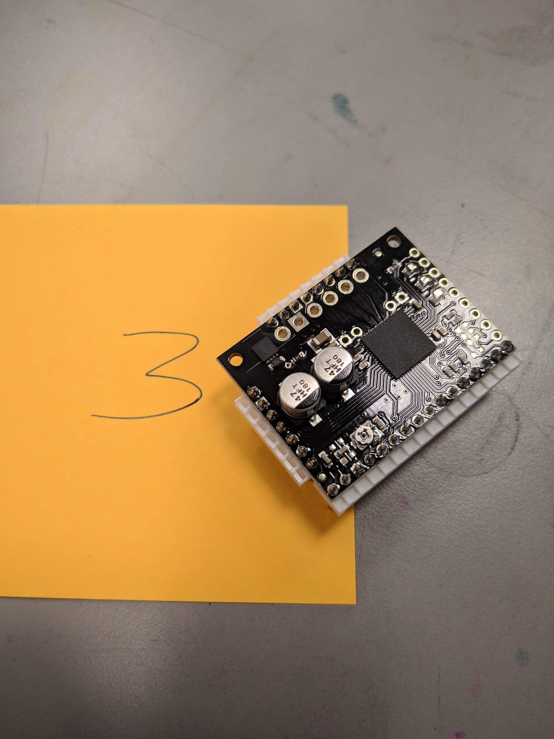
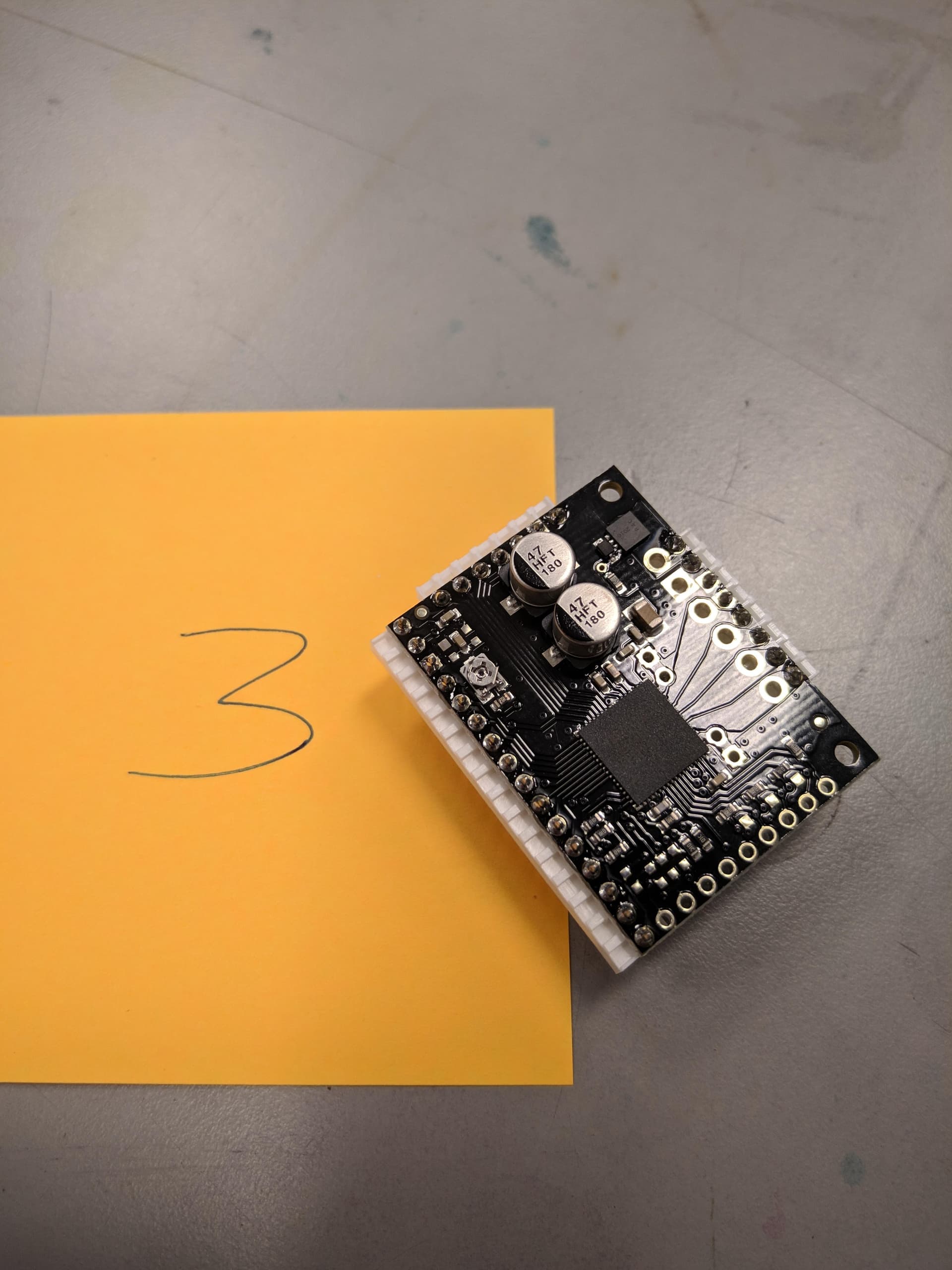
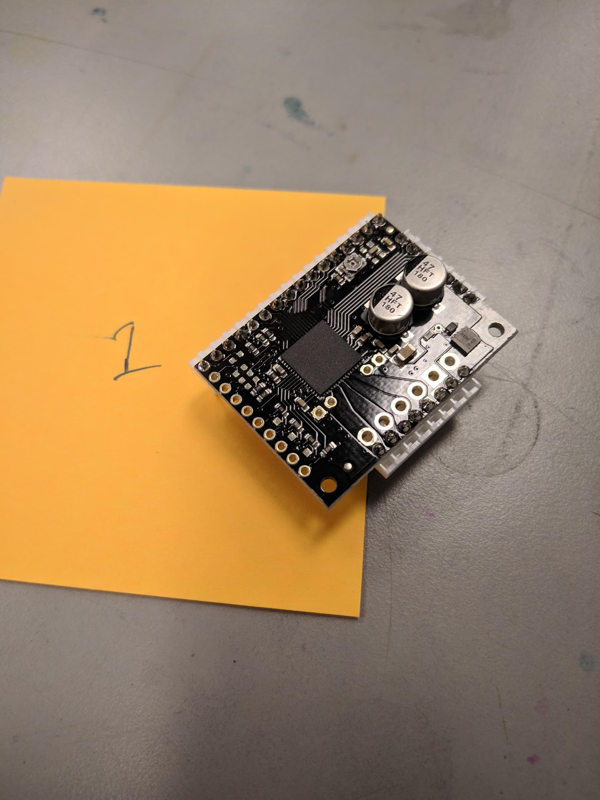
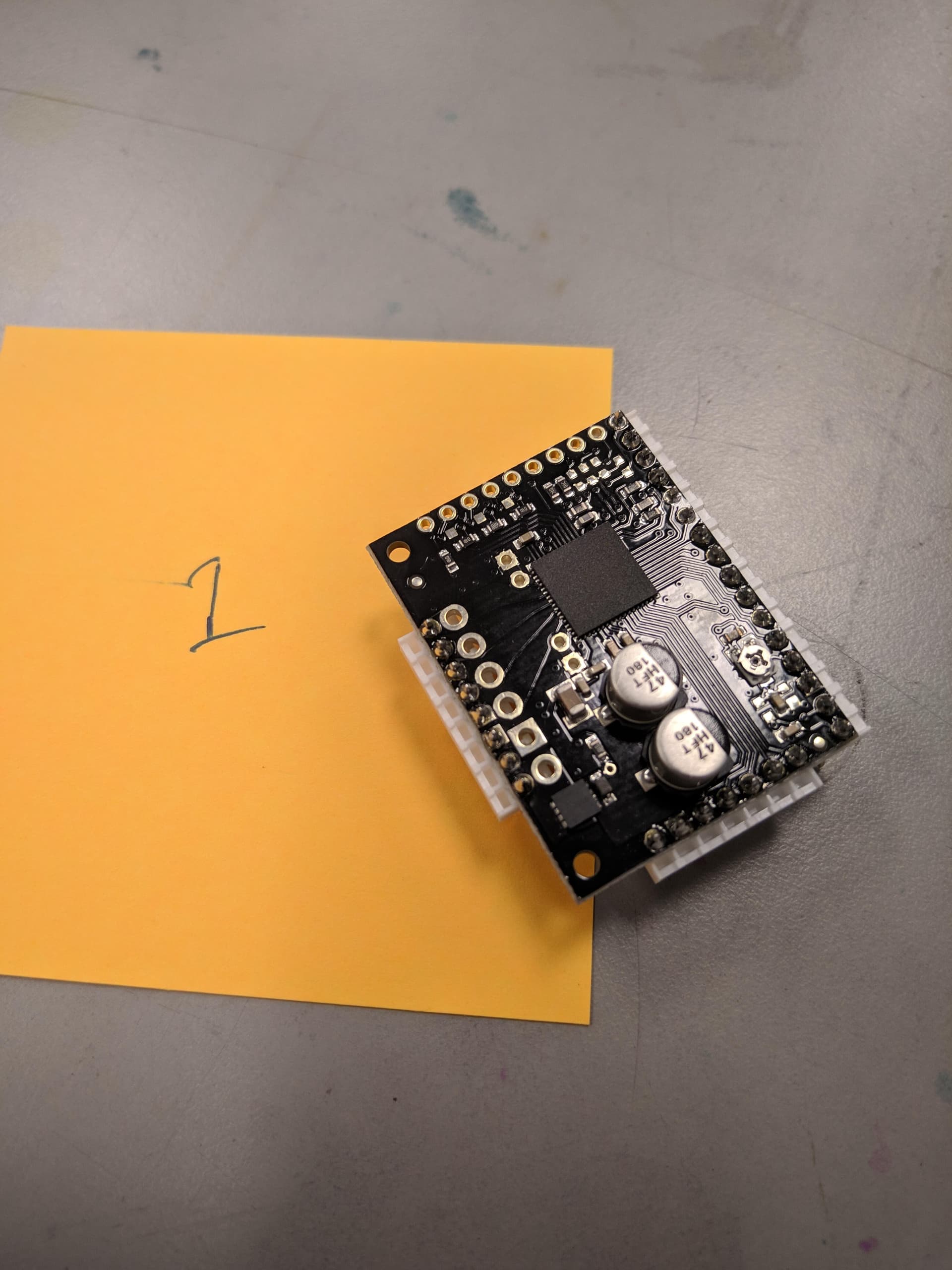
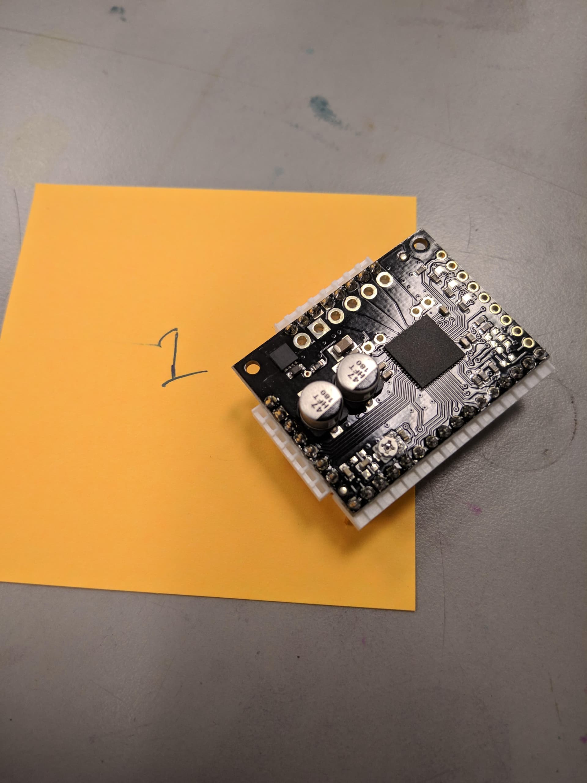
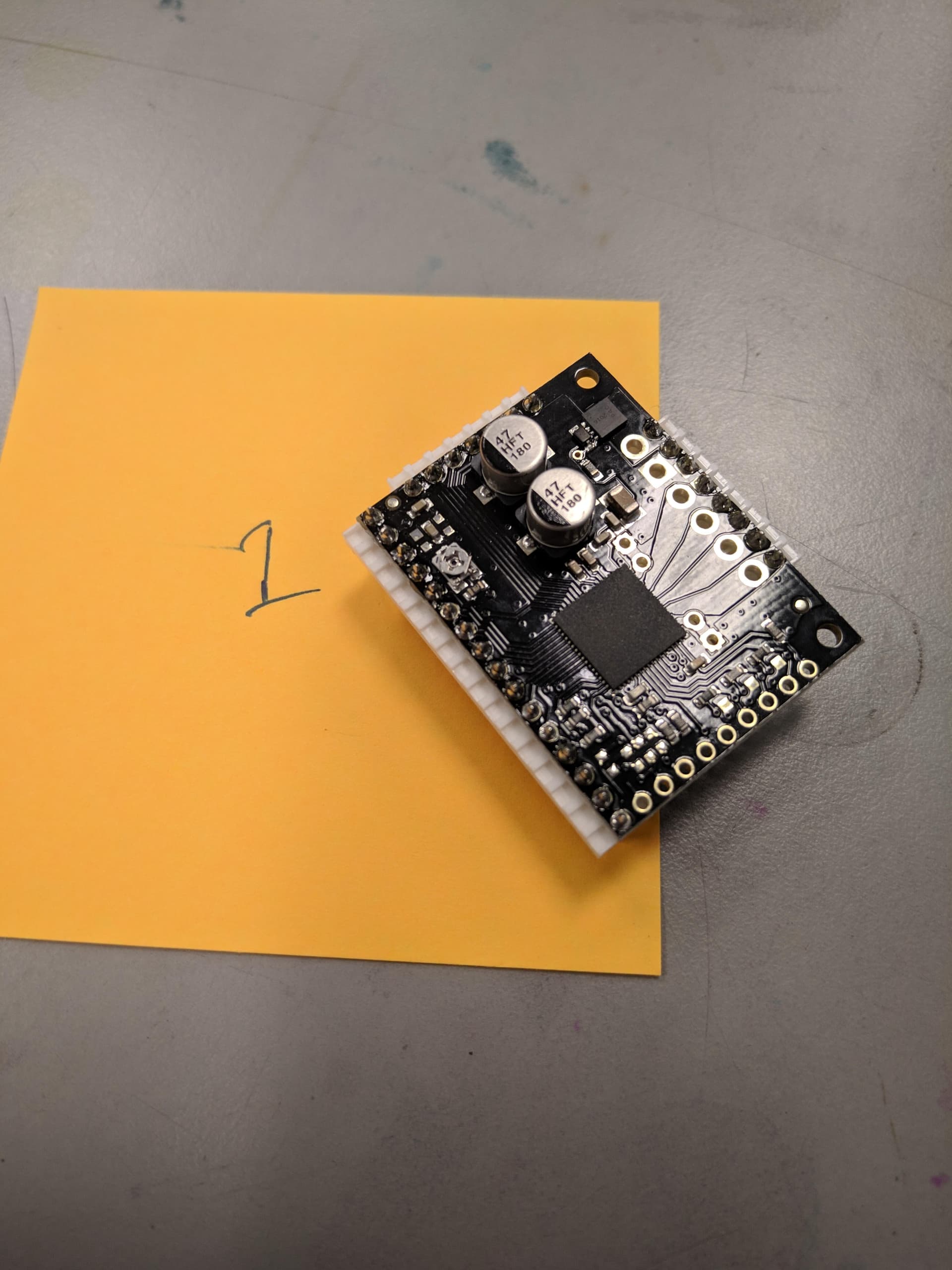
I’ve been having several different problems with the TB67S128FTG Stepper Motor Driver Carrier.
One problem I’ve noticed is the potentiometer has been known to reset itself. There have been a few dozen boards this year with potentiometers that were set correctly and worked for hours, days, and even months before the potentiometers were somehow reset while screwed into a metal board. I know they turned on their own because I started marking them with a sharpie and found that some of those marks had moved when the driver carriers stopped working and the potentiometer was not set to the correct voltage.
Some boards overheat. I’m not sure what’s causing this issue or how to troubleshoot it.
The most common problem, in fact even more common than functional boards, is the motor the carrier is driving simply will not turn. I have tried replacing every other part when this problem arises and it is only fixed by replacing the driver carrier several times.
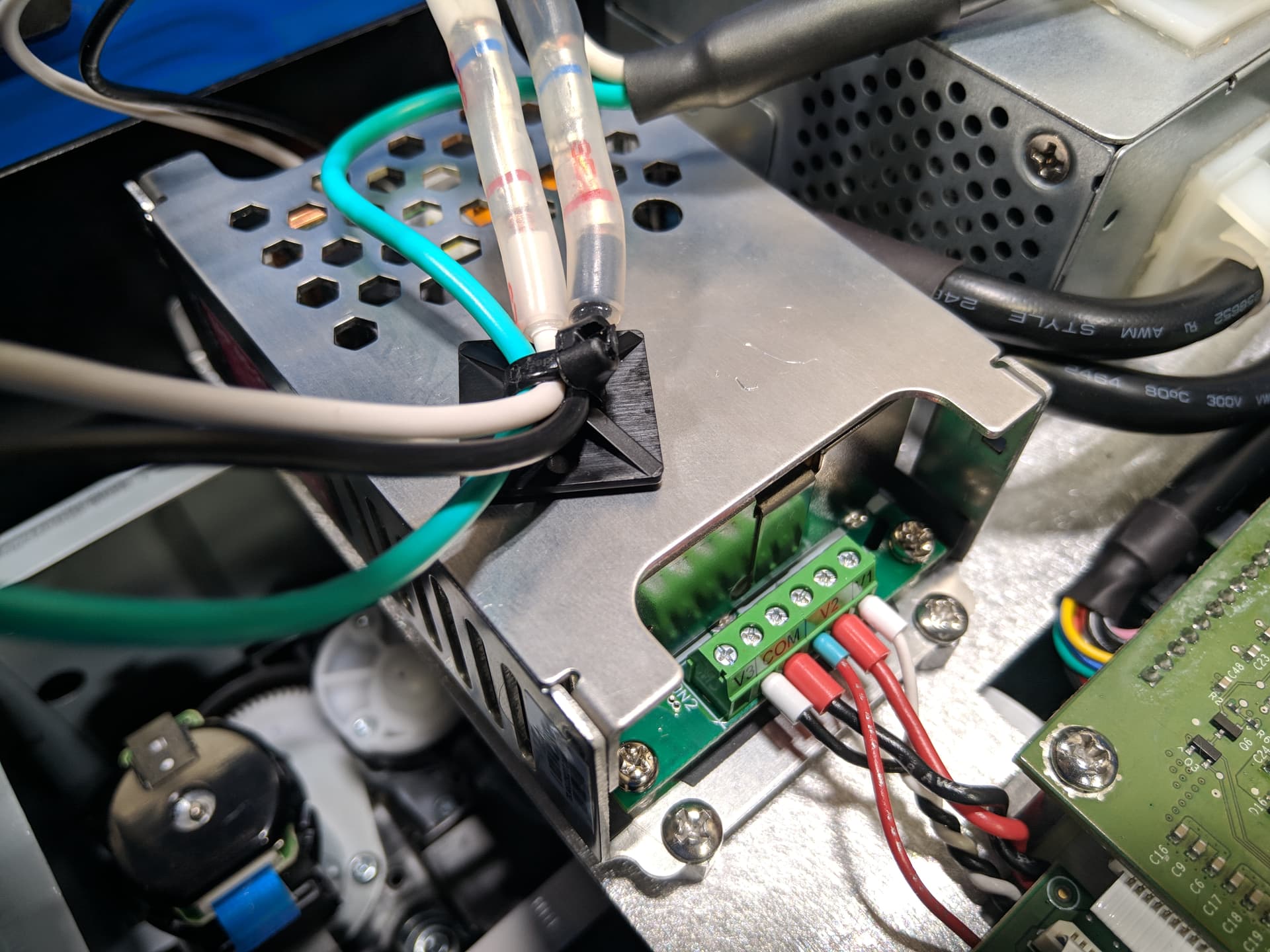
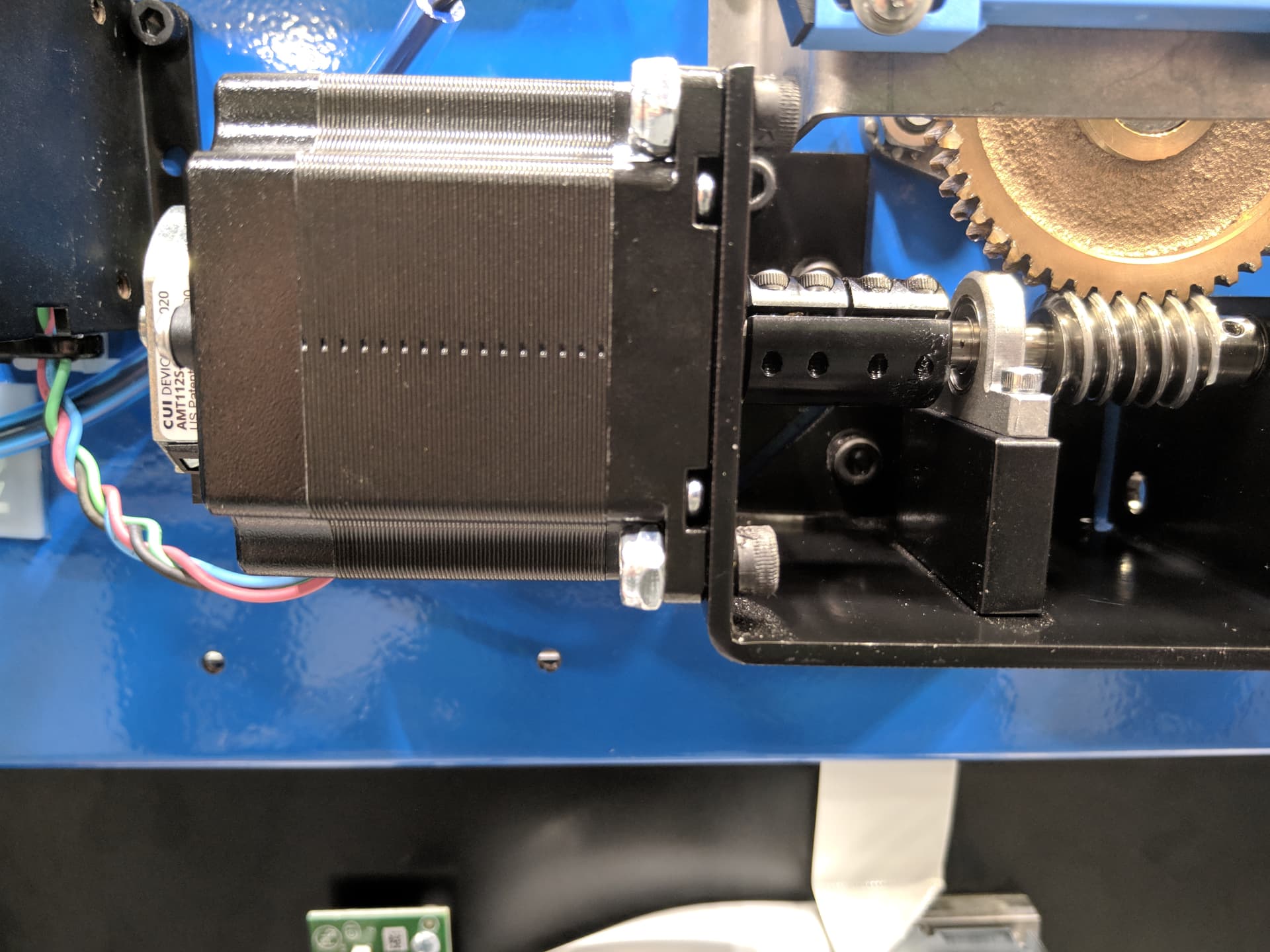
Here’s an overview of the project. Python code implementing the GPIO module or C code implementing the BCM2835 library is running on a Raspberry Pi running Raspberry Pi OS. The Raspberry Pi and driver carrier are both connected to a Traco Power TPP 65-251 power supply (https://www.digikey.com/en/products/detail/traco-power/TPP-65-251/9382127). The driver carrier is driving a NEMA 23-22-02SD-AMT112S stepper motor (https://www.digikey.com/en/products/detail/cui-devices/NEMA23-22-02SD-AMT112S/9477649).
And as for the wiring…
IOREF on the driver carrier is connected to V2 on the power supply.
VIN on the driver carrier is connected to V1 on the power supply.
GND on the driver carrier is connected to COM on the power supply.
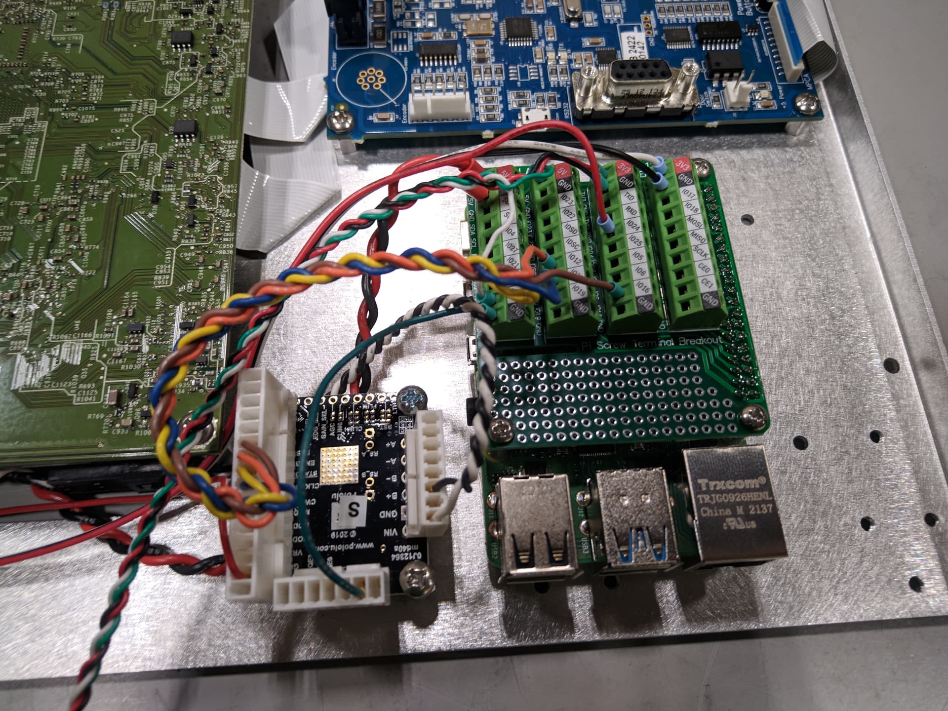
GND on the driver carrier is connected to GND on the Pi.
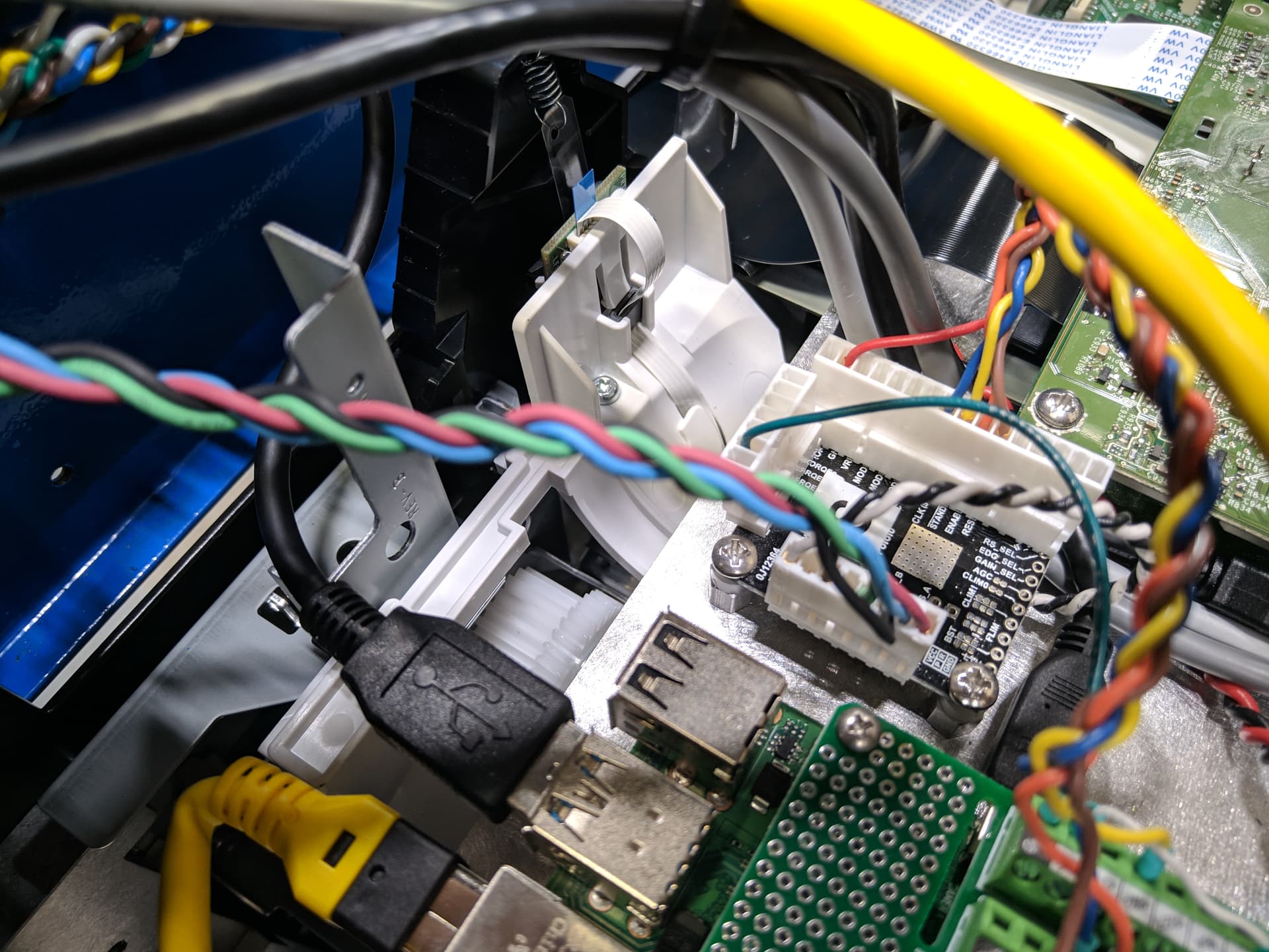
ENABLE on the driver carrier is connected to the Pi GPIO.
STANDBY on the driver carrier is connected to the Pi GPIO.
CLK on the driver carrier is connected to the Pi GPIO.
CW/CCW on the driver carrier is connected to the Pi GPIO.
The algorithm used in both the Python and C programs is as follows:
set ENABLE to HIGH
set STANDBY to HIGH
set CW/CCW to HIGH/LOW
for n steps {
set CLK to HIGH
wait for 800ms
set CLK to LOW
wait for 800ms
}
set ENABLE to LOW
set STANDBY to LOW
The 3rd and most common problem has always been present, but its frequency has significantly increased since the beginning of this year. For a while, the soldering iron was set to 850 degrees F. If there was a change in the frequency of problems after turning this temperature down to 650-700 F, it only increased. The soldered connections are all making good contact.
Immediately after soldering, the board’s potentiometer is set to about 1.34v. The same power supply is used for this. A large number of boards show either 0v or 22+v immediately after being soldered. I do not know if this happens before soldering or only after. Of the boards that show 22+v, some have gone over 30v, which makes no sense to me because the power supply’s range tops out at 24v. When the multimeter displays 0v or 22+v, turning the potentiometer does not affect the voltage. These voltages are constant across every connection on the board.
Of the boards that are correctly set to 1.34v, more than half simply do not turn the motor. When the potentiometer is checked again after trying to turn the motor, the multimeter displays 1.34v, but sometimes displays 0v or 22+v on some boards.
I have tried replacing the power supply, the stepper motor, the Raspberry Pi, the Raspberry Pi SD card, and even the Raspberry Pi hat to no avail. I am at a loss for ideas for further troubleshooting and would appreciate any help.