Hello, to the point:
- control: raspberry pi 4
- language: python3
- driver: (your product) TB67S249FTG
- engine: jk42hm34-1334
Documentation:
What i set:
- input voltage 10V DC
- VREF = 1V (since motor current = 1.33 then: 1.33/ 1.25 = 1.064)
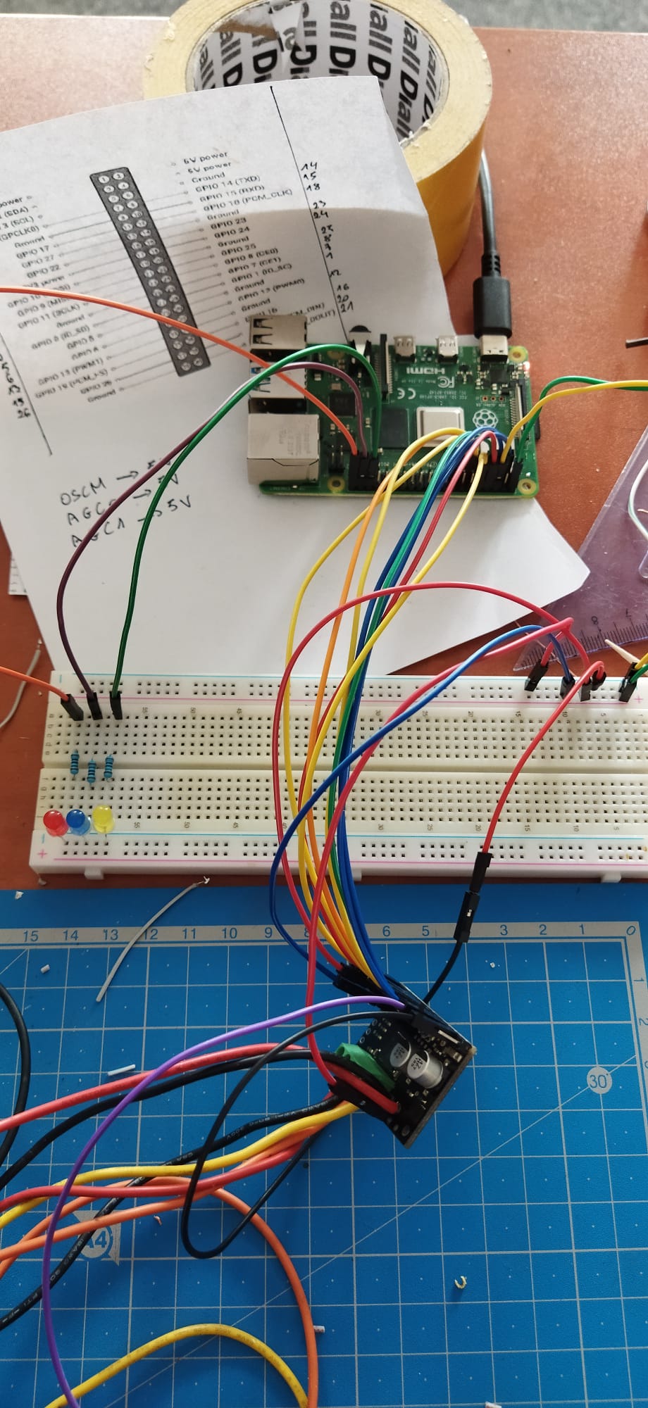
- all GNDs are connected (rpi, right and left driver ground)
Connecting the motor to the driver:
- OUT B+ → RED
- OUT B - → BLUE
- OUT A - → GREEN
- OUT A + → BLACK
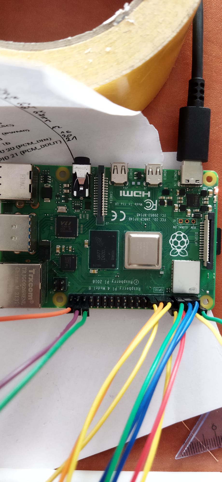
The rest is connected to the Raspberry Pi 4
Engine malfunction:
It works, but as if it’s broken (and it’s new), it squeaks and skips, gets very hot until it’s hot (but the current is regulated)
This motor works on 6V, but on 6V the controller does not work, from 10V it starts to work properly.
The driver was very hot at the beginning! I connected AGC0/1 to 5V and it heats up less, but the motor still does not work as it should.
it all depends on how long you set the gap between CLK (STEP)
if CLK == 5 kHz (0.0002 s)
but when i set time.sleep(.001) (CLK = 1 kHz (0,001 s)
the motor sounds like the current is too great
Do you have any tips for me what I am doing wrong?
If you need any data, I’ll be happy to provide it.
Regards
Hello.
It is normal for stepper motor drivers to heat up and become too hot to touch during normal operation, even when the stepper motor is just energized and holding position. Is there some specific reason you are concerned about the heat? Is the driver’s over-temperature shutdown being triggered?
AGC0 and AGC1 are pulled high on the board by default, so I do not expect driving those high to change anything.
The documentation for your stepper motor does not have a pull-out torque curve, so it is hard to know what to expect from it. It is possible that the 5kHz step rate is more than what is practical to expect from the motor, or you might just be hitting some resonance point. What are you using for your power supply, and is it possible for you to test your setup with a higher voltage?
- Patrick
Hi Patrick!
It is not turned off from too high temperature, it is quite warm (engine). A friend of mine who has worked with BLDC motors for a long time says they shouldn’t get hot like that.
I don’t think so because when I connected them to 5V, the driver system does not heat up so much.
I use a laboratory power supply max 30V [DC], it set the current limit to 5A [DC].
The higher the voltage I gave, the more the controller warmed up.
I tried with 30V [DC] and the effect was the same.
It’s weird how it all works together, but I don’t use the PWM signal, someone taught me in the meantime that I should use it to give the STEP frequency. I’ll try to drive it tomorrow and let you know.
I have one more question.
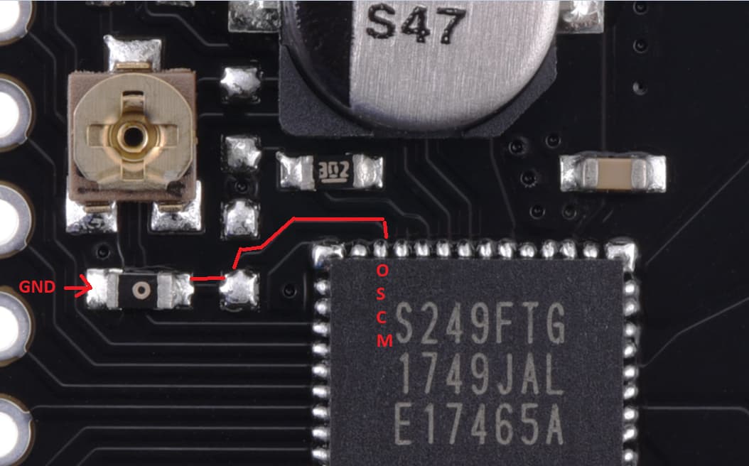
The documentation (https://www.pololu.com/file/0J1523/TB67S249FTG_datasheet_en_20170818.pdf) on page 2 shows the pin layout: 35 pin is responsible for OSCM.
On page 11 it says: “…,Please connect the pull-up resistor to the VCC when PWM
frequency is set by the external components. Also, to use an internal ‘fixed value OSCM frequency’ (not using any external
components), disconnect the ROSC resistor and short the OSCM pin to the GND…” and the wiring diagram of this OSCM is shown (COSC capacitor to GND and ROCS resistor to VCC).
An example of this application with the values of these items is shown on page 23.
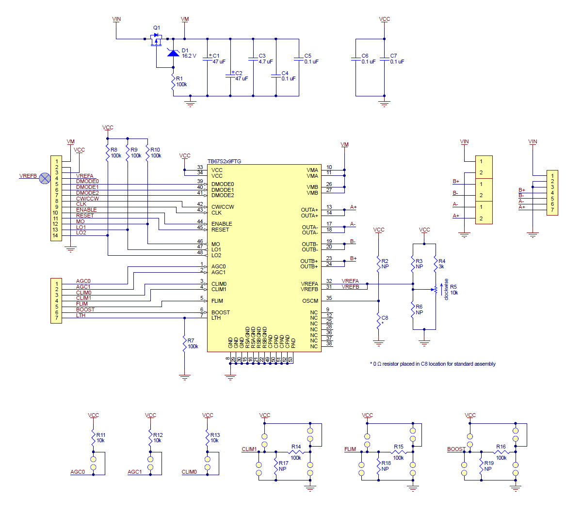
In turn, here is the electronic diagram shown (https://a.pololu-files.com/picture/0J8767.1200.png?be28de2cf3bbc8321be4f60d231458bf), where this COSC capacitor is replaced with a zero Ohm resistor that shorts to ground (GND).
It follows that the signal is permanently generated by the internal oscillator, is this some error in the documentation?
I do not know how hot the components are getting, and that is typically difficult to characterize well anyway (though if you are able to access a good thermal imager that you can use to see how hot things are getting, that would be great). However, as long as the current limit is set properly and the thermal shutdown on your driver is not being triggered, it should be okay. Keep in mind that a stepper motor and stepper motor driver do not work like typical brushless DC motors and drivers; current will flow through the coils whenever they are energized, not just whenever the motor is turning.
If you got the same results with a higher voltage, then another thing you could try is implementing some kind of acceleration routine to ramp up the speed. However, if powering the motor with 30V did not produce any noticeable improvement, then I suspect your motor might just not be intended to operate at those speeds. It might also change when you have a load attached; depending on your load, it could act as a flywheel and help the motor spin once it gets up to speed.
It is also possible there might be some problem with the step signals from your Raspberry Pi since they are typically not well suited for timing sensitive tasks, so it might be good verify that those are okay by checking them with an oscilloscope. If you do not have access to an oscilloscope, another option would be to test your driver with a microcontroller that is more reliable for tasks like this, such as an Arduino.
By default we populate our TB67S249FTG carrier with the OSCM being shorted to GND through a 0Ω resistor as you described which means that the driver will use the internal fixed value OSCM frequency. As far as I can tell, everything in the documentation seems consistent. What do you think is incorrect?
- Patrick

