So I picked up a project that I have been enjoying and breezing through until it came to controlling a DC motor with the Arduino. I am using an Arduino Uno with the Pololu Dual Motor shield remapped for a single channel. All the remap adjustments were made according to the user’s guide. My boards currently are set up with a test motor and I’m only using M1 for an output into a DPDT to reverse polarity on the motor. I am very new to this so it’s likley that I’m missing something stupid obvious.
My problem is that the motor is too fast so i tried this template which was also listed in the user’s guide.
#include "DualVNH5019MotorShield.h"
// configure library with pins as remapped for single-channel operation
// this lets the single motor be controlled as if it were "motor 1"
DualVNH5019MotorShield md(2, 7, 6, A0, 2, 7, 12, A1);
void setup()
{
md.init();
// remaining setup code goes here
...
}
void loop()
{
// loops endlessly; main loop goes here
// the following code is a simple example:
md.setM1Speed(200); // single-channel motor full-speed "forward"
}
This doesn’t seem to slow my motor. I can set it to 400 and get full speed, I can set it to 0 and get it to stop but I can’t seem to get anything between.I just want one slow paced speed. Also I’m not very clear what the line //remaining setup code goes here… is referring too.
Could you tell me more about your setup? What happens when you try to set a speed between 0 and 400? How do you have things connected? Could you post a wiring diagram and pictures of your setup?
By the way, you should be able to change the direction of the motor using the motor driver by setting the speed to a negative value. Is there another reason you are using a DPDT switch?
This seems to get me the speed I want but I did wind up frying the board. I plan on putting a set of pulleys in place to decrease the load coming off my winch. Also I would like to put heat sinks across the two VHN5019 chips and the two 4N03L03 chips. Is there any way for me to get the measurements of these components?
I used the set of relays to forward and reverse because I only have one on off on key switch going into the Arduino so I wasn’t sure how to program it that way. The relays work for now.
The library should have worked with that shield; that issue combined with your other board being damaged makes me suspect that there is something wrong in your setup. I don’t think that the board was damaged because of overheating since it has over temperature protection.
Could you tell me about your setup? How has your setup changed since your first post? Did you change the wiring or did you just change the code? What motor are you using? Do you know its rated voltage and stall current? Could you post pictures and a wiring diagram of your current setup?
I’m using the vnh5019 to control the speed of a winch. The winch is 750W and was the only 12vdc low power(lowest) winch I could get my hands on. The winch draws a load, apparently, higher than what I anticipated. I tested it with an ammeter and it was drawing about 20A continuous without PWM until it reached the top where it gets easier to pull. At say 100 microseconds on and 100 microseconds off the winch would stall out half way up. But if i went to 50 on and 50 off the winch would work. I don’t know how the on time or off time affects the power.
Currently I have an on off on key switch going to a SPST to isolate the switch and a DPDT to control direction. I’m only using M1A/B out of the shield since direction is being controlled by my key switch.
I do realize that the winch is a very high power item to control with this board but my goal is to always keep the current lower than what the pololu is capable of. The only thing I have changed since the first set up is the code. I’m working on drawing the diagram out for you now but its pretty basic.
That motor is probably pushing the limits of what the motor driver is capable of, and I suspect the winch motor drew too much current and damaged the motor driver. You might consider implementing acceleration limiting the to limit current draw, since the current drawn when the motor starts and changes direction can be orders of magnitude higher than the free-run current.
In addition to the wiring diagram, could you also post pictures of your setup so I can check your connections for single channel operation?
OK i have done away with the the relays because if i can control forward and reverse from Arduino I would much rather do that. I’m starting from square one and have remapped my vnh5019 like this for single channel use.
#include "DualVNH5019MotorShield.h"
// configure library with pins as remapped for single-channel operation
// this lets the single motor be controlled as if it were "motor 1"
DualVNH5019MotorShield md(2, 7, 6, A0, 2, 7, 12, A1);
void setup()
{
md.init();
// remaining setup code goes here

}
void loop()
{
// loops endlessly; main loop goes here
// the following code is a simple example:
md.setM1Speed(400); // single-channel motor full-speed "forward"
delay(5000); // wait for 2 seconds
md.setM1Speed(0); // single-channel motor stop (coast)
delay(5000); // wait for 0.5 s
md.setM1Speed(-400); // single-channel motor full-speed "reverse"
delay(5000); // wait for 2 seconds
md.setM1Speed(0); // single-channel motor stop (coast)
delay(5000); // wait for 0.5 s
}
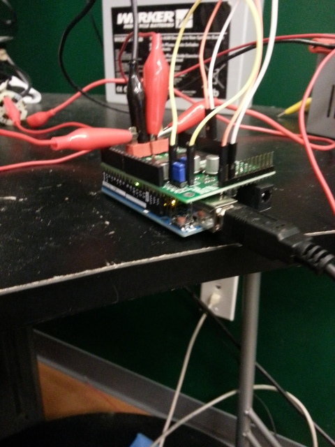
I’m using a 12V power source to Pololu and PC power source to Arduino and a 4-18V DC motor as the load. The result is that the motor only rotates one direction and motor LEDs will illuminate and flicker both green on red on each channel. I always receive 10-11.5v out of M1A/B and M2A/B at the same time. My pololu is brand new and my Arduino is brand new. Any idea of whats happening here?
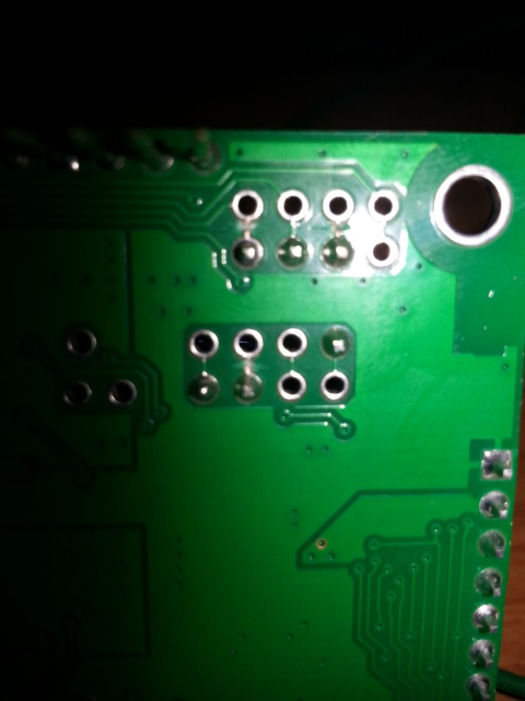
It is hard to tell from your pictures if your traces are cut all the way. Could you test the traces with a multimeter to confirm that the default connections have been severed? Could you also post pictures of your setup that show how the motor is connected and how your Arduino is connected to the VNH5019 shield?
None of these clips are touching. I have M1B going to one side of the motor and M2A going to the other side of the motor.
I can see that it only spins the motor one way and will occassionally sputter in the other direction. The speed control works great. When the speed is set positive I have 11.3 coming out M1 and 8.6 going in M2. Which sounds correct to me. However, when the speed is set to negative I get 11.6V on both M1 and M2. I feel like somewhere in this thing something is connected that shouldn’t be but I have triple checked myself with the user’s guide. I went further and check each individual output and input.
In ( + ) speed
M1A - 11.67v
M1B - 11.67v
M2A - 0v
M2B - 0v
M1INA - 5v
M1INB - 5v
M2INA - 0v
M2INB - 0v
Did you take those measurements without the motor connected? If not, could you try taking them with the motor disconnected? Could you also measure what the PWM pin is doing in both the cases that you tried? If you have access to an oscilloscope, could try to measure across each motor output channel and ground and post a screenshot?
Those readings were taken without the motor. I do not of have access to an oscilloscope. I believe the best I could do is get a voltage reading that the multimeter sees. Of course, M1PWM and M2PWM are the same for each reading. Almost nothing seems consistent with this. The reverse will work for a second, next time it will sputter. next time it wont work at all. With one side on OUTA or OUTB and the other to ground the thing works fine. I don’t want to call the VNH5019 bad but its not adding up to me.
It sounds like the driver might be broken, but I would like to do some tests with the driver here myself. I will get back to you tomorrow after I get some results.
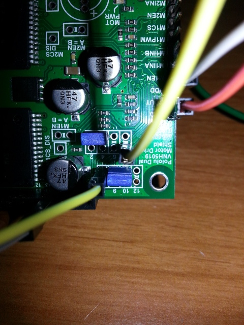
The only thing I have done with this driver is solder the included pins to the board, put Vin, GND and output high current dean style connectors on the right side power holes, remap as the user guide suggests and tested with the demo sketch in the user guide. Please let me know if there is any other information you need.
It sounds like the M1 driver is damaged. Like I said before, that motor is probably pushing the limits of what the motor driver is capable of and might have damaged the motor driver. If you want to try again with a new driver, you can email us with your order information and a reference to this post, and we might be able to help you out with a discount. If you go this route, I recommend you try incrementally testing the shield without the motor connected to verifying everything works both before and after you convert it to single-channel mode. However, if you still plan to use it with your 750W winch motor, you should probably use a more powerful driver instead.
I have not used this board with anything near that power. I have only used it on the bench testing with a tiny 12v dc motor. In fact, I didn’t even connected M1A/B for OUTA and M2A/B for OUTB to run anything high power. Just a routine test to see the sketch in action.
In that case, the more likely explanation might be a bad connection somewhere rather than a damaged driver (though there is still the potential that one of the drivers was inadvertently damaged by something like ESD). In your previous post, you list the measured voltages on all the pins (e.g. M1A, M1INA, etc); where exactly were you measuring the MxINy voltages?
I took measurements from the logic connections on the left side of the board. This seems like it would be out of the VNH5019, a shorted connection but I don’t see any shorted solder joints. I would say the surface mount on one of the VNH5019 is a little questionable but would still appear to be functional, to me. I feel like i’m starting to spend too much time with trying to troubleshoot this board. Is it possible to ask where a reading was taken and suggest a course of action in a single post? I very much believe I have received a defective product. If its not possible to exchange this one for a new one I will just have to bite the bullet and purchase anther.
We test every board before we package it, so it was probably working at some point, and you have made substantial modifications to it since then that are much more likely to be responsible for any problems than some initial defect. If you choose to try again with a new board, I suggest you verify its basic functionality in its default state before introducing complications like remapping pins or connecting potentially overpowered motors.
As I mentioned earlier, if you would like to try again, you can email us with your order information and a reference to this post, and we might be able to help you with a discount.
With the force of weight and the pulley systems in place I draw 19 amps continuous with spike of 30 on start. I will take your suggestion and verify the board in default state. We all learn from our experience!
Thanks for your patience, I certainly appreciate your help with this matter. I think I will give it another shot.