I have a Dual VNH 5019 Motor Shield that I have not used for about 5 years. I tried to use it again on my project and it doesn’t work. I tried the Demo program on the Arduino and it just gives a fault for M1 and stops. Is there anything I can do to get around that fault?
Can you post some pictures of your dual VNH5019 shield and explain more about how you are trying to use it (like what power supply and motors you are using with it)? Are there any connections that have been cut, such as to remap Arduino connections as described in the user’s guide?
Per the third observation you listed something definitely seems wrong. The resistance between pin 6 and the M1ENA/B should only be 1kΩ (as it is between M2ENA/B). With that connection apparently broken, pin 6 will be stuck in a floating state instead of being pulled high by default, which would explain why the program is indicating an error, Can you try measuring the resistance between M2ENA/B and the Arduino 5V pin?
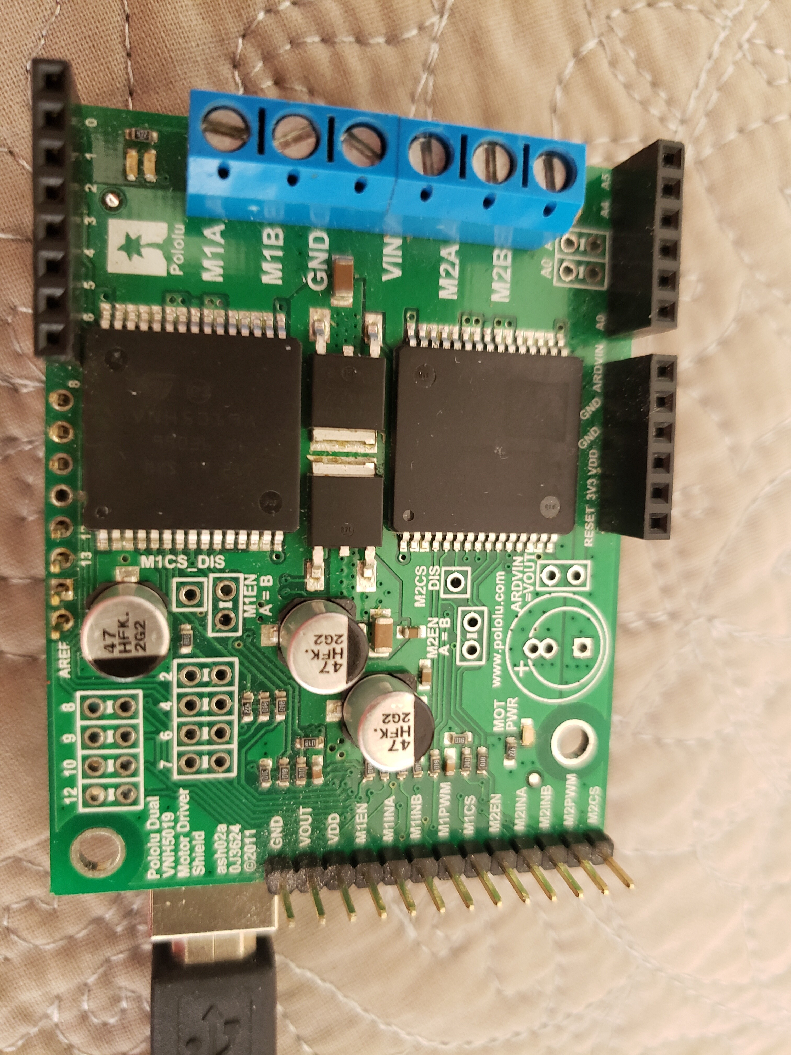
Patrick, thanks for your reply. Here is a picture of the shield. I had to take off one of the female header strips after a wire got stuck in it. But I replaced it with some male pins, though I have not soldered them in and the connection to the shield may not always be solid. (Perhaps that is a problem, but the shield worked for several years after that.) I did not ever re-map any of the pins.
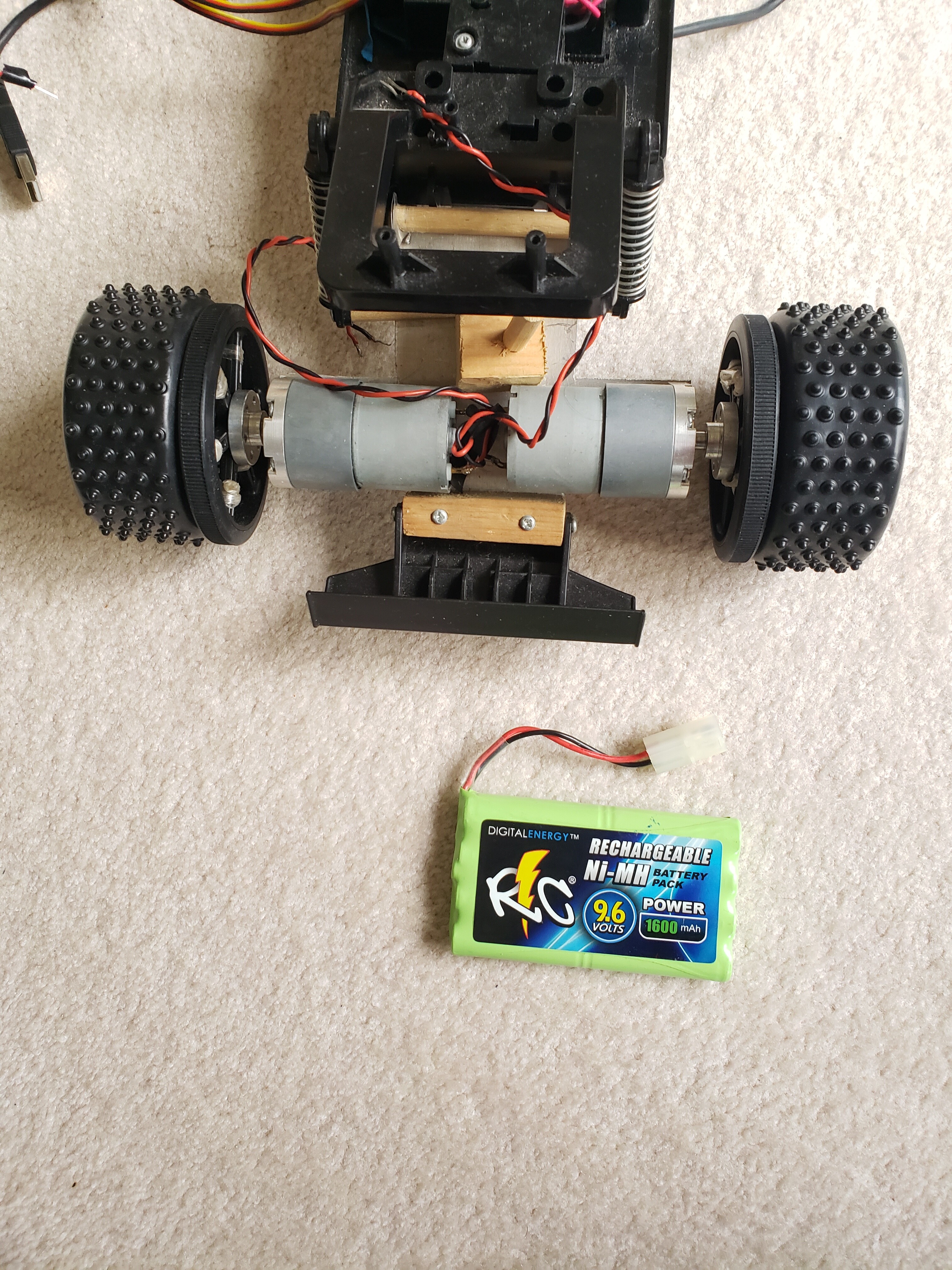
Here are the motors I use and the power supply. They are 12V Pololu 19:1 gearmotors 37Dx52L. The power supply is 9.6 Volts. The shield worked with this power supply and these motors for several years.
But I haven’t tried them for the last four years. When I did hook them up, the Arduino I was using did not work and I had to replace that. But even after I did that the motor shield does not work at all.
I removed all connections from the shield and ran the Demo the motor lights do not turn on. That’s true even if I just run the code in the Demo for Motor2. Only the blue LED labeled “Motor Power” turns on.
You said “Can you try measuring the resistance between M2ENA/B and the Arduino 5V pin?” Between M2EN A=B and the Arduino 5V pin is 4.6K Ohms.
Also, I tried measuring again between pin 6 and M2EN A=B. It is now an open circuit (before it was 2.6M Ohms).
Thanks for the additional information. I am surprised that your board functioned for so long with several pins being unsoldered like that. Unsoldered pins can cause intermittent connections and potentially damaging voltage spikes, so even though it is probably unrelated to the issue you are experiencing now, I would not try to use your board until after all the pins are soldered. Also, it seems like you might be working on a fabric or carpeted surface. Please keep in mind that electronics like these can be damaged by things like stray voltages and electrostatic discharge (ESD), so if you have a more suitable work area I strongly recommend using it.
Sorry, I made a mistake and meant to ask you what the resistance is between M1ENA/B and the Arduino 5V pin since that is the driver in question. Can you measure that instead? Can you also confirm that the high resistance or open circuit measurements you reported are between M1ENA/B and pin 6, not M2ENA/B (and if they were from M2, can you measure from M1 instead)?
Thanks again for your help. As you recommended I soldered in the pins. I will also be more careful where I place the circuit boards to avoid static charges.
As to the resistance measurements, the resistances were the same whether I measured from M1EN A=B or M2EN A=B.
That is, between M1EN A=B and the Arduino 5V pin the resistance is 4.6K Ohms (the same as between M2EN A=B and the Arduino 5V pin).
Between M1EN A=B and pin 6 is an open circuit (the same as between M2EN A=B and pin 6).
The only difference is that between M2EN A=B and pin 12 the resistance is 1.0K Ohms, but between M1EN A=B and pin 12 the resistance is 10.2K Ohms.
From what you say, it seems that the readings for M2 are normal, but the readings for M1 are not. I have two questions.
Why doesn’t the LED on the motor shield for M2 light up when I run the Demo program that only tries to turn on M2?
Is there anything to do to try and get the board working again or do I need to buy a new one?
Thanks for the clarifications. The reading between M1ENA/B and the Arduino 5V pin is normal, so I think what is happening is the EN pins on the driver are probably being pulled high to enable the driver (like they should be), but since pin 6 is totally disconnected, your Arduino code is getting caught in the fault condition.
Can you try testing your driver with this program? It is the same as the demo program from our library, but the M1 fault trigger is commented out.
#include "DualVNH5019MotorShield.h"

DualVNH5019MotorShield md;

void stopIfFault()
{
  /*
  if (md.getM1Fault())
  {
    Serial.println("M1 fault");
    while(1);
  }
  */
  if (md.getM2Fault())
  {
    Serial.println("M2 fault");
    while(1);
  }
}

void setup()
{
  Serial.begin(115200);
  Serial.println("Dual VNH5019 Motor Shield");
  md.init();
}

void loop()
{
  for (int i = 0; i <= 400; i++)
  {
    md.setM1Speed(i);
    stopIfFault();
    if (i%200 == 100)
    {
      Serial.print("M1 current: ");
      Serial.println(md.getM1CurrentMilliamps());
    }
    delay(2);
  }

  for (int i = 400; i >= -400; i--)
  {
    md.setM1Speed(i);
    stopIfFault();
    if (i%200 == 100)
    {
      Serial.print("M1 current: ");
      Serial.println(md.getM1CurrentMilliamps());
    }
    delay(2);
  }

  for (int i = -400; i <= 0; i++)
  {
    md.setM1Speed(i);
    stopIfFault();
    if (i%200 == 100)
    {
      Serial.print("M1 current: ");
      Serial.println(md.getM1CurrentMilliamps());
    }
    delay(2);
  }

  for (int i = 0; i <= 400; i++)
  {
    md.setM2Speed(i);
    stopIfFault();
    if (i%200 == 100)
    {
      Serial.print("M2 current: ");
      Serial.println(md.getM2CurrentMilliamps());
    }
    delay(2);
  }

  for (int i = 400; i >= -400; i--)
  {
    md.setM2Speed(i);
    stopIfFault();
    if (i%200 == 100)
    {
      Serial.print("M2 current: ");
      Serial.println(md.getM2CurrentMilliamps());
    }
    delay(2);
  }

  for (int i = -400; i <= 0; i++)
  {
    md.setM2Speed(i);
    stopIfFault();
    if (i%200 == 100)
    {
      Serial.print("M2 current: ");
      Serial.println(md.getM2CurrentMilliamps());
    }
    delay(2);
  }
}
Patrick, it works! The M1 and M2 drivers now work and I am able to power both my motors. But I’m not sure what happened to make them work. I had tried the same thing before and got no LEDs lighting up or any motors turning.
When I tried your Demo code the motor LEDs flashed green and red like they are supposed to. And I got this on the Serial Monitor:
When I uncommented code and put the M1 fault check back in, the program would stop at that fault and say “M1 fault” on the serial monitor.
Seeing the LED lights working, I hooked everything back up again and tried it, and things work fine. I’m not sure what changed. Could soldering in those pins have made a difference? I don’t see how, but I can’t think of anything else that could have either.
I did check the resistance between M1EN A=B and pin 6 again, and it is now at 11M Ohms rather than an open circuit. But it is still far from being at 1K Ohms like it is supposed to be, and still gives a fault on M1.
Thanks for all your help! I’ll keep using the driver shield and see what happens.
Just to clarify, are you saying that the driver now sometimes works even if you leave the M1 fault trigger code active? As I mentioned before, the connection to M2ENA/B broken pin 6 is probably stuck in a floating state (i.e. it could be either high or low) so seeing inconsistent results like that is not too surprising.
I agree that soldering the pins probably did not affect this since pin 6 is not included in the group of pins you soldered. I am not sure what might have damaged the connection between pin 6 and M2ENA/B after all this time. Other then the unsoldered connections we already addressed, I did not see any issues from inspecting the picture of the top of your board, but if you want to post a picture of the bottom of your board too, I can let you know if anything stands out there.