
Hello. Could you please clarify whether or not Dual VNH5019 Motor Driver Shield for Arduino Pololu Dual VNH5019 Motor Driver Shield for Arduino can be used for two gimbal 12V DC 3-phase electromotors with encoders? Thank you.
Hello.
It sounds like you are referring to some 3-phase brushless DC (BLDC) motors; if that is the case, a typical dual H-bridge driver like the VNH5019 is not appropriate. You might consider our recently released A89301-based sensorless brushless motor controller; however, please note that since it is sensorless, it cannot use the encoders directly. If you post more details about your motors, such as a link to a product page or datasheet, I would be happy to take a closer look.
Brandon
Hello Brandon. We want to use two gimbal 12V DC 3-phase electromotors with encoders Gimbal Motor with Encoder - 12V, 467RPM - SparkFun Electronics To control the electromotors, we want to use A-Star 32U4 Mini SV controller board Pololu - A-Star 32U4 Mini SV if we will use two VNH5019 motor drivers Pololu - VNH5019 Motor Driver Carrier instead of the Dual VNH5019 motor driver shield for Arduino. After testing with the two electromotors, we will use the four electromotors. Our project is similar to this https://www.youtube.com/watch?v=3ozgxPi_tl0 In the video, she uses four VNH5019 motor drivers connected to four electromotors with encoders! Thank you.
Please note that those gimbal motors are a fundamentally different type of motor than the ones used in that YouTube video. Those gimbal motors are 3-phase brushless motors (which the VNH5019 is not compatible with), while the ones in the YouTube video are simple brushed DC motors with encoders (more specifically, our 19:1 37D 12V gearmotors with encoders according to the video’s description).
You could probably drive each gimbal motor with a A89301-based controller that I mentioned in my previous post (e.g. one for each of those gimbal motors), but as I noted, it will not be able to use the motors’ integrated encoder. Alternatively, you might try checking with SparkFun to see what kind of driver they recommend.
Brandon
1 Like
Hello Brandon. As I think, the best microcontroller boards for gimbal motors with encoders are STM32 boards based on this article Microcontrollers | Arduino-FOC . I suppose to use STM32 NUCLEO-64 with STM32F401RE MCU https://www.st.com/en/evaluation-tools/nucleo-f401re.html .
Because we use the 24V battery, I will use Pololu 9V 5A Step-Down Voltage Regulator D42V55F9 Pololu - 9V, 5A Step-Down Voltage Regulator D42V55F9 to power the two gimbal 12V motors via two Sparkfun 3-Phase Brushless Motor Drivers (TMC6300) SparkFun Brushless Motor Driver - 3-Phase (TMC6300) - SparkFun Electronics .
Based on the specifications, the motor driver and the microcontroller board should work well with Arduino Simple Field Oriented Control library https://docs.simplefoc.com/
I would much appreciate any your comments.
At this point, the only Pololu product you are asking about is our step-down regulator, and I suspect powering one or two of those motors from a D42V55F9 regulator to generally work fine.
As far as the rest of the system, I do not have any specific recommendations or advice. Is there a particular reason you want to use brushless motors? As noted on the SparkFun TMC6300 driver’s product page that you linked to controlling 3-phase brushless motors is not trivial; you will need 6 PWM signals per motor, plus additional considerations for integrating the feedback signals.
Brandon
Hello Brandon. There is not a very particular reason to use brushless motors. For our project, we just need pancake-shaped electromotors with encoders. Pancake shape is significant for our project. We also need electromotors with good torque, not high torque though. The Sparkfun gimbal motors are good for us.
In the video that I provided to you, she explains how to make code (with PID control) to control electromotors.
Hello Brandon,
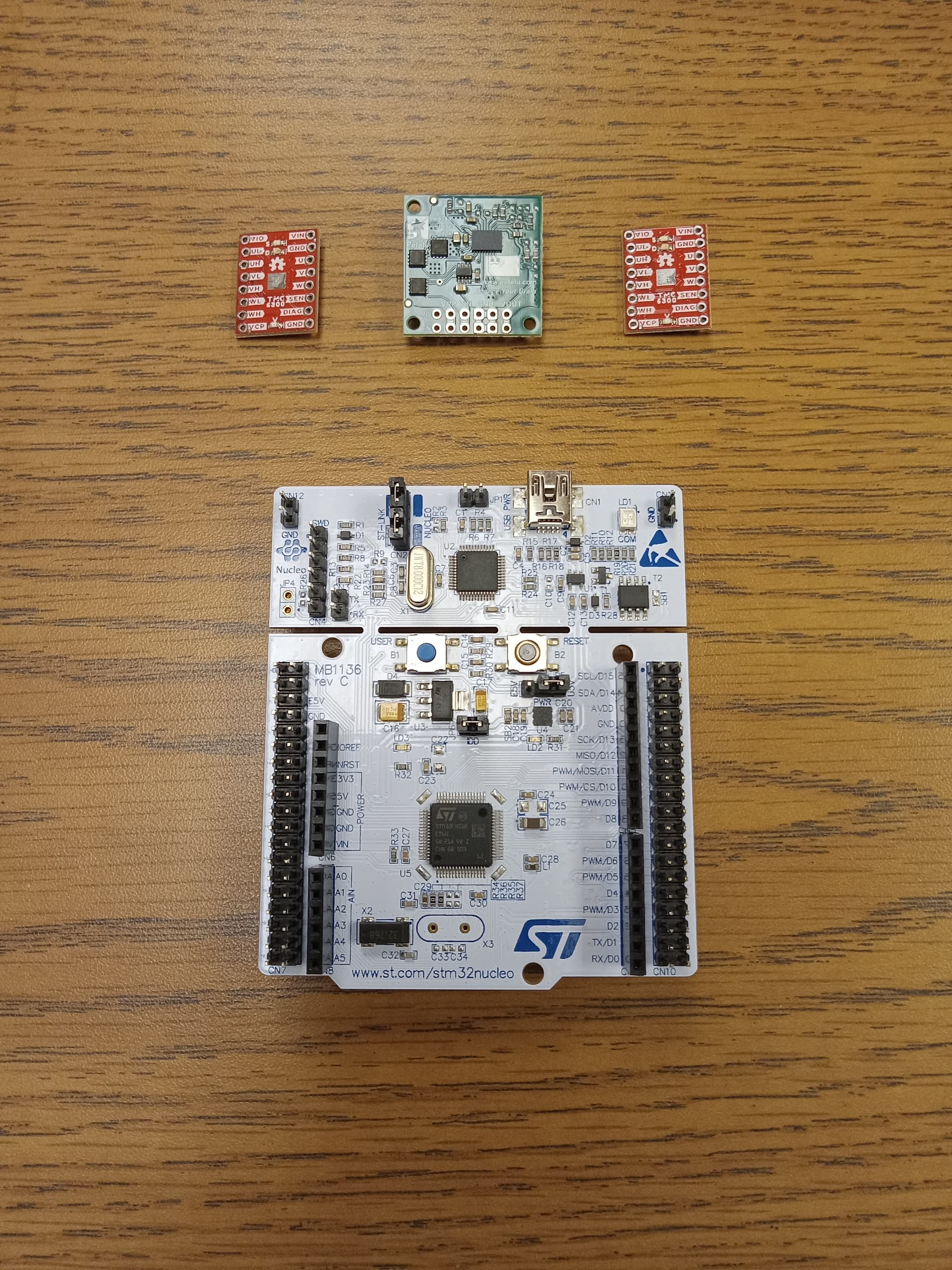
Could you please tell how to connect your Pololu D42V55F9 regulator to the Sparkfun TMC6300 motor-drivers and the STM32 NUCLEO-64 microcontroller board, please see the attached photos of their front and back sides? Thank you.
I am not very familiar with those other devices you are using, but for reference you can find an explanation of what each pin on the D42V55F9 regulator is for under the “Connections” section of its product page.
In the simplest usage, if you just want to step your input voltage down to 9V (and do not need to enable/disable the regulator or monitor the power state), you can just connect your input power source to the VIN and GND pins and then connect whatever you want to power to VOUT and GND.
From a quick look at the documentation for the those other devices, it looks like SparkFun’s TMC6300 board is powered through its VS and GND pins, and the NUCLEO board is powered through the VIN and GND pins.
Brandon
Thank you, Brandon. For our project, we need to shut off the power for particular periods of time (very short periods - milliseconds). Therefore, we will probably need to use enable/disable pins. The point is that if the microcontroller board is programmed to set the zero speed, the motors are fixed at some position. We do not need them to be fixed. We need them to rotate freely. So, we will probably need to disable your voltage regulator for some milliseconds.
Hi Brandon,
I checked the section, however, I still have questions. There are two VIN pins on the voltage regulator. Could you please clarify what is the second VIN pin for? To connect a second power source? Thank you.
I do not know the specifics of your system, but disabling the regulator while the motors are energized sounds like it could lead to problems and potentially damage to the system. Additionally, the timing of the system powering off or back on when the regulator is disabled might not be as fast as you are hoping for. Ultimately, disabling the motors like you described is probably much better off being handled by your motor driver instead of toggling motor power; does the driver you are using have an option to disable the motors?
As far as the two VIN pins, they are identical and connected internally, so you can use either one. There is no specific intent for the duplicate pin, but it can be handy in some situations. For example, it can be convenient way to power other devices from your input voltage without having to run another wire back to your power source.
Brandon
Hello Brandon,
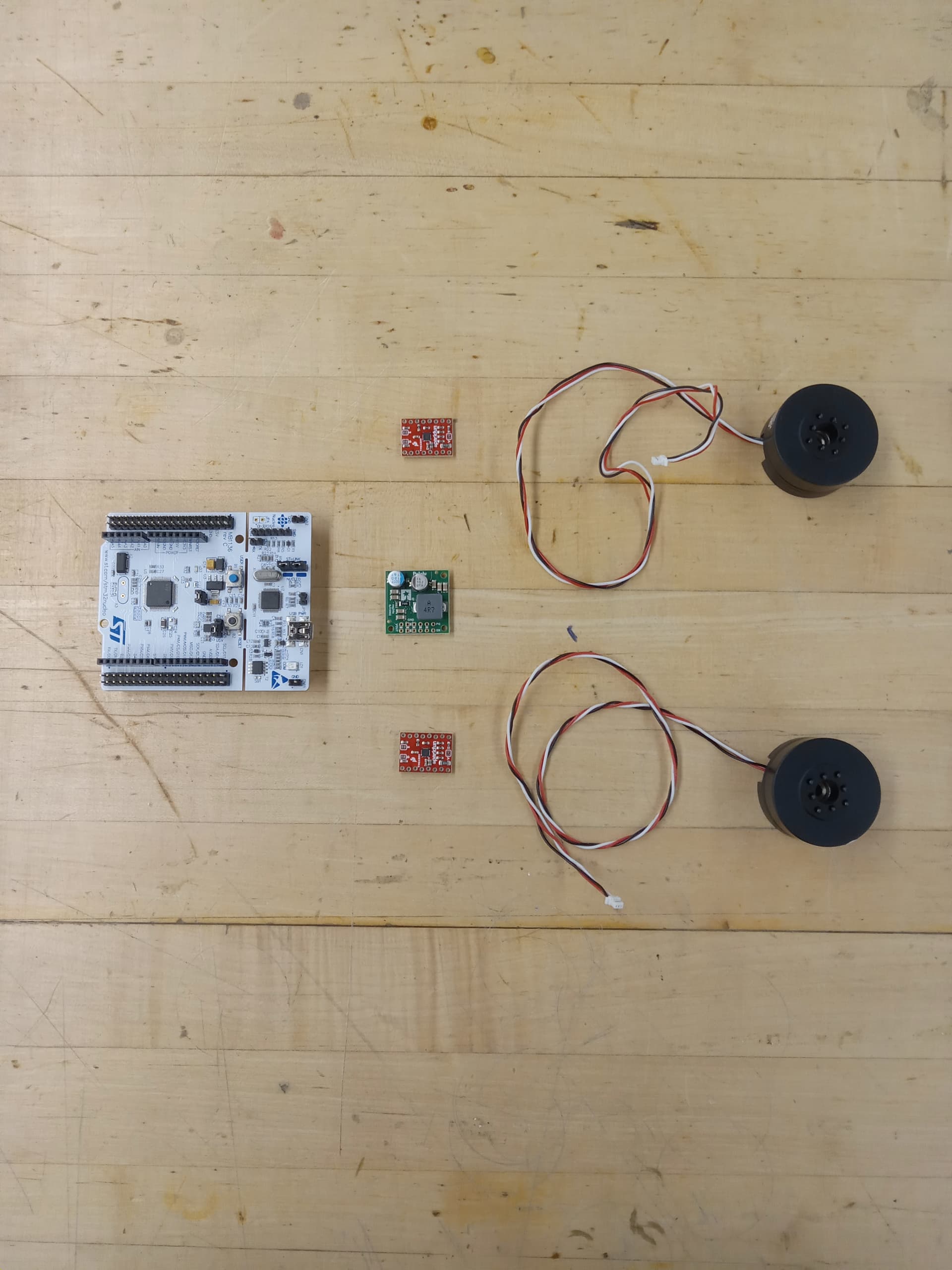
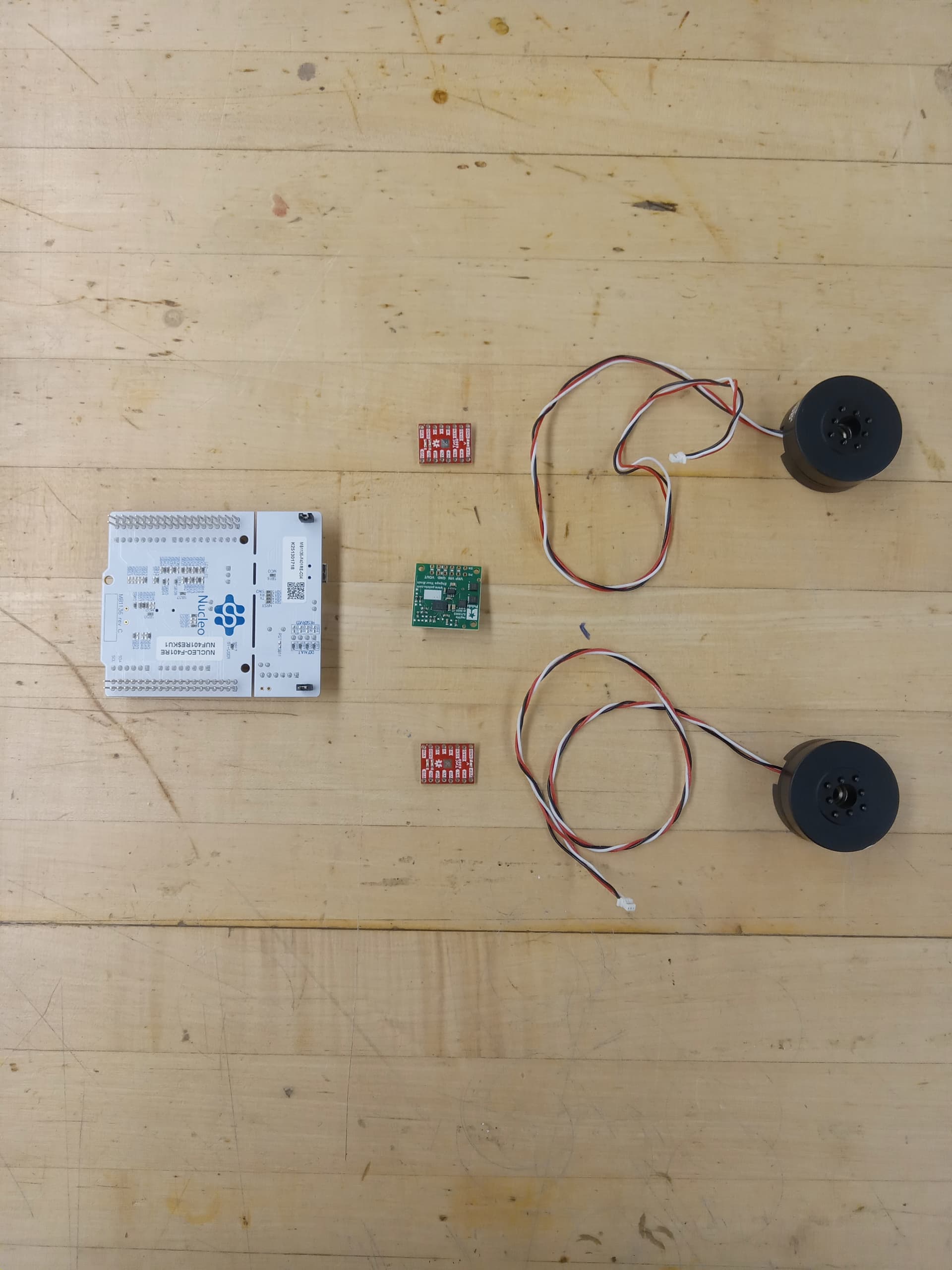
Please see the photo attached. These are all the components of our system, except the 24V battery. I do not think that the motor-driver has any enable/disable pin. Therefore, I suppose it is impossible to disable the motor-driver.
If the second VIN pin can be used to power the microcontroller board, it is great. How much volts and amperes does the second VIN pin supply? Thank you.
Hello Brandon,
Just in case if you missed my last question. I answer your question and Please see the photos that I attached above. These are all the electronic components of our system, except the 24V battery. I do not think that the motor-driver has any enable/disable pin. Therefore, I suppose it is impossible to disable the motor-driver. Though, I still learn the driver’s full-discription datasheet.
If the second VIN pin can be used to power the microcontroller board, it is great. How many volts and amperes does the second VIN pin supply? Thank you.
Sorry for the delayed response; I must have missed your previous reply.
I do not see any attached picture to your post, but as I mentioned in my previous post, the VIN pins are directly connected to each other internally. So, connecting it to your microcontroller would essentially be the same as connecting your 24V battery directly to your microcontroller. From a quick search, it looks like the STM32 Nucleo-64 has an operating voltage of 7-12V, so you should not use 24V (doing so would probably damage it immediately). Instead, you can power it from the regulator’s VOUT (which also has two pins available) to supply it with 9V.
Brandon
Thank you, Brandon. The attached is the photo of all the electronic components (except a 24V battery) of our system. One cannot power the microcontroller board from the regulator VOUT because the two electromotors have to be powered by impulses. So if we turned on and off the regulator frequently, it would not work for the project. The board has to be powered permanently during the system’s operational time. I think to power the microcontroller board directly from the 24V battery by just using a large resistor.
Hello.
It would be very unusual for a driver board like that to not offer a way to disable the motor outputs. For example, it looks like it breaks out the driver’s VIO_NSTDBY pin that can be used to stop the motors. You could also try seeing what happens when the input signals for the 3 coils are all low. However, as I mentioned before, I am not very familiar with that SparkFun TMC6300 board, so I recommend checking with SparkFun directly to see what they recommend.
If there really is no way to disable the motor outputs and you want to try toggling power from the regulator, I recommend using a separate step-down voltage regulator or a separate power supply to safely power the microcontroller. You should not use a large resistor to power a microcontroller from a higher voltage.
Brandon