Hello,
I am using 2x VNH5019 motor drivers (#2507) with an Arduino Mega to drive 3x 37D gearmotors with encoders (#2507) at 12V. The code I am using is relatively simple, comparing current encoder position with a “set point,” and spinning the motor in the right direction until the “set point” has been reached within a given tolerance. When it is 2.0 and 0.5 turns away from the “set point” respectively, the motor will slow down to a slower and then minimum speed. Originally, this was working perfectly and I was able to get the motor to seek my “set point” within a tolerance of 5 counts.
Because I am planning to have a eventually have long connection between the drivers and the motors (~15 feet of wire), I then soldered two additional 330uF 35C capacitors (#882) onto each driver, as well as a 0.1uF ceramic (#2451) across the poles of the motor. However this is when my issue started.
Now, running the same code, once the motor has neared the “set point,” it begins to bounce, oscillating between backwards and forwards 3-5 times before stopping. Right now, it will still settle and stop eventually, but if I increase the minimum speed it will seemingly oscillate indefinitely.
My guess is that adding capacitance to the system has created an lag between the Arduino issuing commands and them reaching the motor, which might be causing the oscillations. Is that likely? Is there another explanation, and/or workaround for this?
So far I have tried (with the issue persisting):
- Decelerating the motor earlier, further away from the “set point”
- Increasing the tolerance around the “set point”
- Decreasing/increasing the minimum speed
I am using the updated Arduino library specifically for driving 2 of these shields (DualVNH5019MotorShieldMod3). While I have shuffled around some of the GPIO pins, the PWM pins remain at their defaults.
Have you extended the wires to their final length yet, or are these problems appearing just after adding the capacitors? Please post some pictures of your setup, including ones that show all of your connections and where you added capacitors.
At this point we can only guess at what is happening. If possible, I suggest you try testing your system in four configurations to see if you can narrow down the cause of the problem:
- With both capacitors
- With neither of the additional capacitors (to confirm the problem does go away)
- With only the 330µF capacitor
- With only the 0.1µF capacitor
Then monitor your setup with an oscilloscope so we can see what is really going on. Can you post screen captures of what you find?
- Patrick
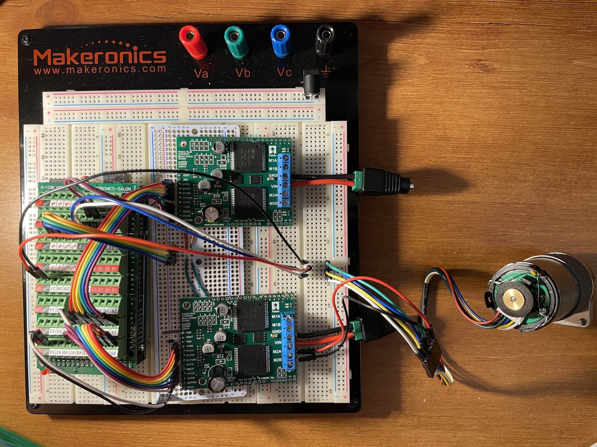
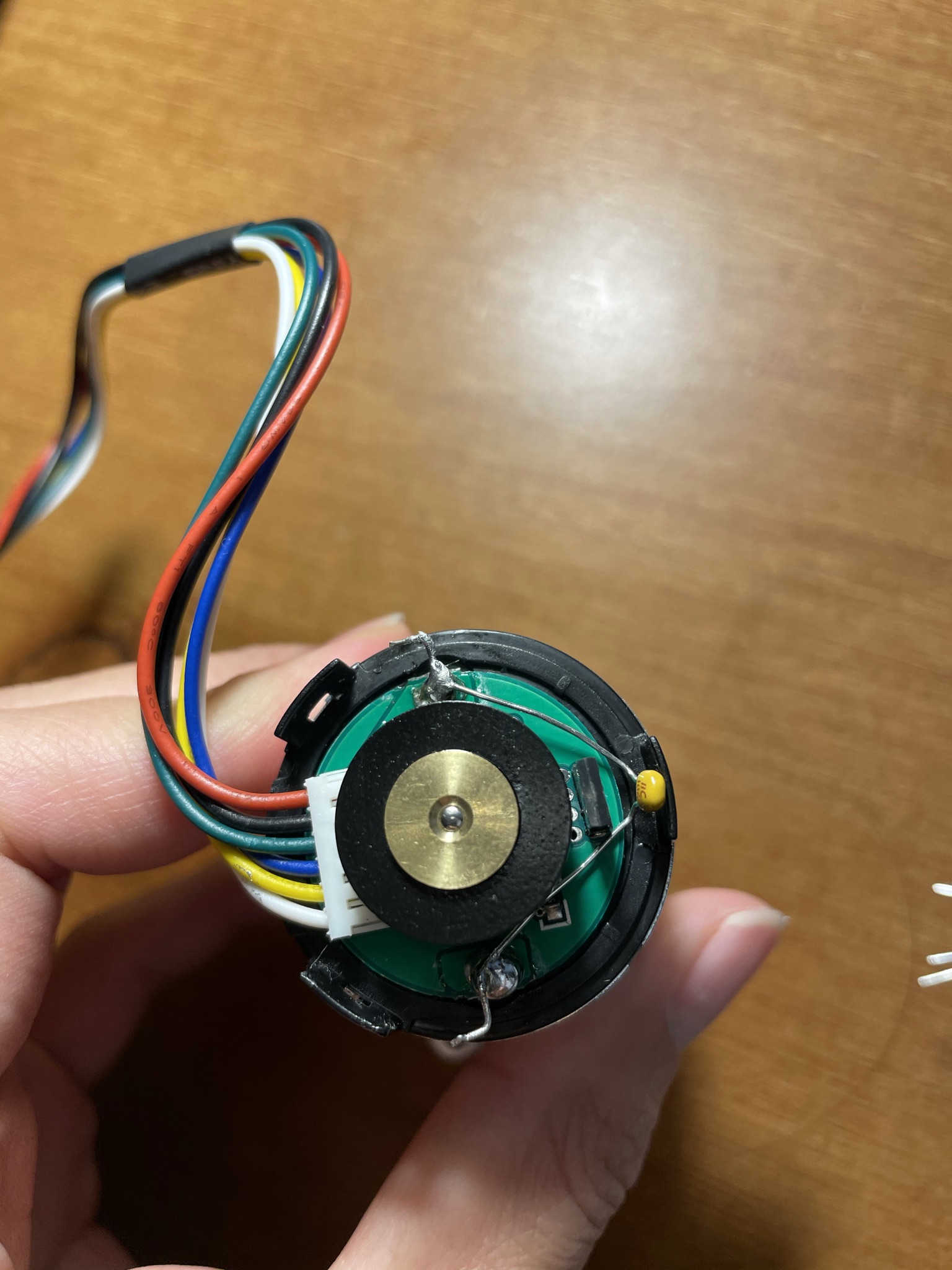
Thanks, Patrick. I’ve posted a few photos of my setup below. As you can see I haven’t yet extended the wires to their final length, but I have already begun soldering some components to perma-protos (and was hesitant to desolder them). Nonetheless, it had to be done  I popped one of the drivers off onto a breadboard.
I tested as you suggested and am now truly stumped - in all 4 scenarios (including in which all add’l capacitors were removed), the problem persists. I even rolled-back my code to a previous version and still see the oscillations. I’m now worried that I might have permanently damaged a motor or driver in the process of soldering the capacitors on.
Unfortunately I don’t have access to an oscilloscope to see what’s happening. Save for buying a fresh motor/driver, is there anything else you think I might be able to test?
Hello.
If you are running the same physical setup and same program as you were before but are still experiencing the same error, then your control method which was working before is probably not as robust as you thought. It seems like your system was probably right on the threshold of being unstable.
With that in mind, I do not expect getting a new motor or driver is a sure way to resolve the issue. Instead, you should probably try to implement a more robust control algorithm, like PID control.
- Patrick
Got it, that makes sense.
Is there a preferred PID library/implementation to use with the VNH5019? I gave it a (brief) attempt earlier in this project, but had some difficulty with tuning.
Thanks so much, Patrick.
Unfortunately, we do not have any specific resources for implementing PID position control with motor drivers and encoders, but there are probably a lot of resources and examples from others who have made similar systems out there. You could also look at the LineFollower example program from the Arduino library for our Zumo 32U4 Robot as a general example of how to implement a PD control routine in Arduino.
As far as tuning your PID controller goes, one common approach for that is the Ziegler-Nichols method. But like the general implementation, there are probably multiple strategies that could help you reach a good result.
By the way, in case you are not thinking of it already, I recommend tuning your system’s PID constants while your motors are carrying the actual loads they will need to handle in your application. The exact loading conditions on your motor will impact the ideal PID constants.
- Patrick