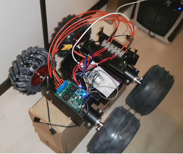
Sorry for the late reply,
The modifications are not really note worthy. Basically I changed the PWM Pins in the header file, as they are different on the Feather M0 bord. While doing so I also changed the pin numbers in the cpp file in order to fit them to the Feather.
As for the MxCS Pins, I will give it a try this weekend.
#ifndef DualVNH5019Mod_h
#define DualVNH5019Mod_h

#include <Arduino.h>

class DualVNH5019MotorShield
{
  public:
    // CONSTRUCTORS
    DualVNH5019MotorShield(); // Default pin selection.
    DualVNH5019MotorShield(unsigned char INA1, unsigned char INB1, unsigned char EN1DIAG1, unsigned char CS1,
                           unsigned char INA2, unsigned char INB2, unsigned char EN2DIAG2, unsigned char CS2); // User-defined pin selection.

    // PUBLIC METHODS
    void init(); // Initialize TIMER 1, set the PWM to 20kHZ.
    void setM1Speed(int speed); // Set speed for M1.
    void setM2Speed(int speed); // Set speed for M2.
    void setSpeeds(int m1Speed, int m2Speed); // Set speed for both M1 and M2.
    void setM1Brake(int brake); // Brake M1.
    void setM2Brake(int brake); // Brake M2.
    void setBrakes(int m1Brake, int m2Brake); // Brake both M1 and M2.
    unsigned int getM1CurrentMilliamps(); // Get current reading for M1.
    unsigned int getM2CurrentMilliamps(); // Get current reading for M2.
    unsigned char getM1Fault(); // Get fault reading from M1.
    unsigned char getM2Fault(); // Get fault reading from M2.

  private:
    unsigned char _INA1;
    unsigned char _INB1;
    static const unsigned char _PWM1 = 5;
    unsigned char _EN1DIAG1;
    unsigned char _CS1;
    unsigned char _INA2;
    unsigned char _INB2;
    static const unsigned char _PWM2 = 6;
    unsigned char _EN2DIAG2;
    unsigned char _CS2;

};

#endif
and for the cpp:
#include "DualVNH5019Mod.h"

// Constructors ////////////////////////////////////////////////////////////////

DualVNH5019MotorShield::DualVNH5019MotorShield()
{
  //Pin map
  //MODIFIED IN ORDER TO SUIT M0 FEATHER BLE
  _INA1 = 12;
  _INB1 = 11;
  _EN1DIAG1 = 13;
  _CS1 = A0;
  _INA2 = 0;
  _INB2 = 22;
  _EN2DIAG2 = 1;
  _CS2 = A1;
}

DualVNH5019MotorShield::DualVNH5019MotorShield(unsigned char INA1, unsigned char INB1, unsigned char EN1DIAG1, unsigned char CS1,
                                               unsigned char INA2, unsigned char INB2, unsigned char EN2DIAG2, unsigned char CS2)
{
  //Pin map
  //PWM1 and PWM2 cannot be remapped because the library assumes PWM is on timer1
  _INA1 = INA1;
  _INB1 = INB1;
  _EN1DIAG1 = EN1DIAG1;
  _CS1 = CS1;
  _INA2 = INA2;
  _INB2 = INB2;
  _EN2DIAG2 = EN2DIAG2;
  _CS2 = CS2;
}

// Public Methods //////////////////////////////////////////////////////////////
void DualVNH5019MotorShield::init()
{
// Define pinMode for the pins and set the frequency for timer1.

  pinMode(_INA1,OUTPUT);
  pinMode(_INB1,OUTPUT);
  pinMode(_PWM1,OUTPUT);
  pinMode(_EN1DIAG1,INPUT);
  pinMode(_CS1,INPUT);
  pinMode(_INA2,OUTPUT);
  pinMode(_INB2,OUTPUT);
  pinMode(_PWM2,OUTPUT);
  pinMode(_EN2DIAG2,INPUT);
  pinMode(_CS2,INPUT);
  #if defined(__AVR_ATmega168__)|| defined(__AVR_ATmega328P__) || defined(__AVR_ATmega32U4__)
  // Timer 1 configuration
  // prescaler: clockI/O / 1
  // outputs enabled
  // phase-correct PWM
  // top of 400
  //
  // PWM frequency calculation
  // 16MHz / 1 (prescaler) / 2 (phase-correct) / 400 (top) = 20kHz
  TCCR1A = 0b10100000;
  TCCR1B = 0b00010001;
  ICR1 = 400;
  #endif
}
// Set speed for motor 1, speed is a number betwenn -400 and 400
void DualVNH5019MotorShield::setM1Speed(int speed)
{
  unsigned char reverse = 0;

  if (speed < 0)
  {
    speed = -speed;  // Make speed a positive quantity
    reverse = 1;  // Preserve the direction
  }
  if (speed > 400)  // Max PWM dutycycle
    speed = 400;
  #if defined(__AVR_ATmega168__)|| defined(__AVR_ATmega328P__) || defined(__AVR_ATmega32U4__)
  OCR1A = speed;
  #else
  analogWrite(_PWM1,speed * 51 / 80); // default to using analogWrite, mapping 400 to 255
  #endif
  if (speed == 0)
  {
    digitalWrite(_INA1,LOW);   // Make the motor coast no
    digitalWrite(_INB1,LOW);   // matter which direction it is spinning.
  }
  else if (reverse)
  {
    digitalWrite(_INA1,LOW);
    digitalWrite(_INB1,HIGH);
  }
  else
  {
    digitalWrite(_INA1,HIGH);
    digitalWrite(_INB1,LOW);
  }
}

// Set speed for motor 2, speed is a number betwenn -400 and 400
void DualVNH5019MotorShield::setM2Speed(int speed)
{
  unsigned char reverse = 0;

  if (speed < 0)
  {
    speed = -speed;  // make speed a positive quantity
    reverse = 1;  // preserve the direction
  }
  if (speed > 400)  // Max
    speed = 400;
  #if defined(__AVR_ATmega168__)|| defined(__AVR_ATmega328P__) || defined(__AVR_ATmega32U4__)
  OCR1B = speed;
  #else
  analogWrite(_PWM2,speed * 51 / 80); // default to using analogWrite, mapping 400 to 255
  #endif
  if (speed == 0)
  {
    digitalWrite(_INA2,LOW);   // Make the motor coast no
    digitalWrite(_INB2,LOW);   // matter which direction it is spinning.
  }
  else if (reverse)
  {
    digitalWrite(_INA2,LOW);
    digitalWrite(_INB2,HIGH);
  }
  else
  {
    digitalWrite(_INA2,HIGH);
    digitalWrite(_INB2,LOW);
  }
}

// Set speed for motor 1 and 2
void DualVNH5019MotorShield::setSpeeds(int m1Speed, int m2Speed)
{
  setM1Speed(m1Speed);
  setM2Speed(m2Speed);
}

// Brake motor 1, brake is a number between 0 and 400
void DualVNH5019MotorShield::setM1Brake(int brake)
{
  // normalize brake
  if (brake < 0)
  {
    brake = -brake;
  }
  if (brake > 400)  // Max brake
    brake = 400;
  digitalWrite(_INA1, LOW);
  digitalWrite(_INB1, LOW);
  #if defined(__AVR_ATmega168__)|| defined(__AVR_ATmega328P__) || defined(__AVR_ATmega32U4__)
  OCR1A = brake;
  #else
  analogWrite(_PWM1,brake * 51 / 80); // default to using analogWrite, mapping 400 to 255
  #endif
}

// Brake motor 2, brake is a number between 0 and 400
void DualVNH5019MotorShield::setM2Brake(int brake)
{
  // normalize brake
  if (brake < 0)
  {
    brake = -brake;
  }
  if (brake > 400)  // Max brake
    brake = 400;
  digitalWrite(_INA2, LOW);
  digitalWrite(_INB2, LOW);
  #if defined(__AVR_ATmega168__)|| defined(__AVR_ATmega328P__) || defined(__AVR_ATmega32U4__)
  OCR1B = brake;
  #else
  analogWrite(_PWM2,brake * 51 / 80); // default to using analogWrite, mapping 400 to 255
  #endif
}

// Brake motor 1 and 2, brake is a number between 0 and 400
void DualVNH5019MotorShield::setBrakes(int m1Brake, int m2Brake)
{
  setM1Brake(m1Brake);
  setM2Brake(m2Brake);
}

// Return motor 1 current value in milliamps.
unsigned int DualVNH5019MotorShield::getM1CurrentMilliamps()
{
  // 5V / 1024 ADC counts / 144 mV per A = 34 mA per count
  return analogRead(_CS1) * 34;
}

// Return motor 2 current value in milliamps.
unsigned int DualVNH5019MotorShield::getM2CurrentMilliamps()
{
  // 5V / 1024 ADC counts / 144 mV per A = 34 mA per count
  return analogRead(_CS2) * 34;
}

// Return error status for motor 1
unsigned char DualVNH5019MotorShield::getM1Fault()
{
  return !digitalRead(_EN1DIAG1);
}

// Return error status for motor 2
unsigned char DualVNH5019MotorShield::getM2Fault()
{
  return !digitalRead(_EN2DIAG2);
}

