Problem: The motor driver carrier board stopped working after about 5 days of use (not continuously). At least, it appears to be the case.
Hardware:
Dual VNH2SP30 Motor Driver Carrier MD03A (Item#708)
30:1 Metal Gearmotor 37Dx68L mm with 64 CPR Encoder (Item#2823)
Arduino UNO
Software/code:
//motor controller test
//Dual VNH2SP30 pololu #708
//30:1 Metal Gearmotor 37Dx68L mm with 64 CPR Encoder pololu #2823
//Arduino UNO
//red wire +5V UNO, black wire GND UNO
const int INA_2_pin = 9; //grey, Motor 2 direction
const int INB_2_pin = 10; //white, Motor 2 direction
const int PWM_2_pin = 11; //orange, Motor 2 speed

void setup()
{
  pinMode(INA_2_pin, OUTPUT);
  pinMode(INB_2_pin, OUTPUT);
  pinMode(PWM_2_pin, OUTPUT);
}

void loop()
{
  digitalWrite(INA_2_pin,LOW);//direction grey
  digitalWrite(INB_2_pin,HIGH); //direction white
  analogWrite(PWM_2_pin, 255); //speed orange
}
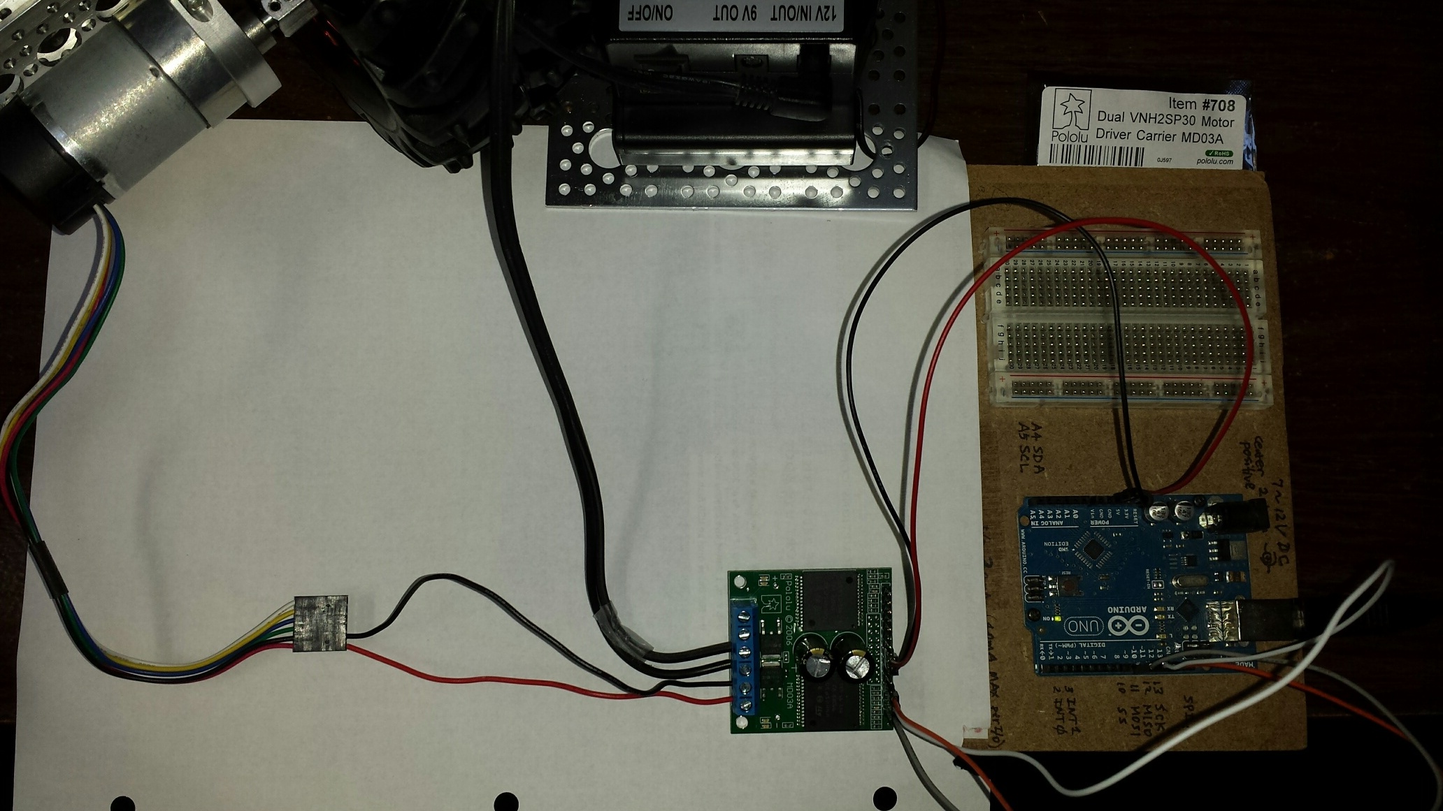
Connections:
UNO +5V -------------- VNH2SP30 +5V(IN)
UNO GND ------------- VNH2SP30 GND (on the logical connection side)
UNO Digital pin 9 -------- VNH2SP30 2INA
UNO Digital pin 10 -------- VNH2SP30 2INB
UNO Digital pin 11 -------- VNH2SP30 2PMW
UNO power (usb port) ----------- Computer USB
12V power (battery pack) ---------- VNH2SP30 VIN(+) and GND(-) (on the motor connection side)
Motor positive terminal ----- VNH2SP30 OUT2B
Motor negative terminal ---- VNH2SP30 OUT2A
Please see attached.
With two motors, didn’t work (tried with ArduinoMega2560 and ArduinoUNO)
With one motor (either output), didn’t work (tried with ArduinoMega2560 and ArduinoUNO)
Tested with a multi-meter, all of the connected power pins and digital pins show correct configured/expected voltage (e.g. 0v, 5v, 12.2v) except OUTPUT 1A/1B and OUTPUT 2A/2B — these 4 pins always shows 0v
During all above tests, all of the lights on the Drive Carrier board were off.
Tested each motor separately with 12v power directly connected to the motors, the motors work.
Background:
The VNH2SP30 worked with Arduino Mega2560 (two motors) in a two-wheel self-balance robot. It stopped working yesterday. To isolate the problem and troubleshoot one thing at a time, I did the UNO-VNH2SP30-motor test setup, and hence the simplified code.
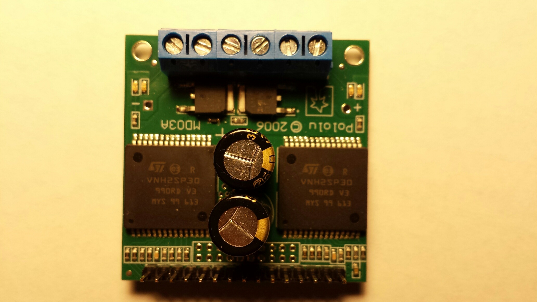
I am sorry your motor driver carrier is damaged; thank you for including a detailed description of what you have tested. Unfortunately, I am not sure what might have been the issue. Can you describe specifically when the driver stopped working (e.g. was the your robot in the middle of balancing, or did the drivers not even successfully start to control their motors)? Can you also post close up pictures of the carrier board that clearly show the VNH2SP30 chips?
After the robot has been powered off (no power connection) for a couple of days (maybe only one day), I connected the power but the motors didn’t move. That’s when I noticed that the motor driver had no lights on, and suspected that the driver might have a problem.
Thanks for the picture. There does not appear to be any damage, so it is difficult to determine what might have happened. In general, electronics like these can be sensitive to things like static shocks, so in case that was the issue, you might double-check that your work and operating environment are not prone to that kind of thing. Also, I noticed your power supply leads look a little long, which makes it easier for something like an LC voltage spike to occur as soon as power is connected in your system. It might be that during a spike like that, the voltage across the inputs on the VNH2SP30s rose above their maximum voltage of 16V, permanently damaging them. In general, to reduce the magnitude of LC voltage spikes, you can use shorter, thicker wires. You can learn more about LC voltages spikes and other ways to limit their magnitude on this web page.
If you email us at support@pololu.com with your order information and a reference to this thread, I can see what we can do to help you out.
Thanks for the information. I’ll study the LC voltage spikes (thanks for the link).
For my education:
In addition to the physical observation of the chips/board, is there any other “simple” way to electronically determine that the chips/board is damaged? I understand that I may not be able to comprehend your answer and/or perform the diagnostics due to my lack of knowledge and/or equipment, but I am curious, if you have time.
Outside of what has been done in this thread there is probably not anything else that is simple that can be done to investigate. The motor driver carrier does not have much other hardware on it that can be used to determine if the problem is with the driver or not. Replacing the VNH2SP30 motor driver ICs could help identify if the issue is with the drivers, but that is not a perfect test, since there is some chance that other parts of the boards are also damaged or not working, too.