I am using the shield with one motor connected to M1. Can anyone verify that using one motor is an accepted use case?
It seems when I run the example program, I get up to 190-210 milliamps on M1 before it sees M1_FAULT then goes into an eternal while loop. Meanwhile, I hear the motor humming but no actual rotation. Oddly, after I hit this condition, if I unplug the M1 power leads then plug them back in to, the motor starts rotating.
I performed the soldering for the Dual TB9051FTG Motor Driver Shield. I used a continuity test on a multimeter, where I touched the inner pins for the IO rails+the mail connector to the Arduino, which had been soldered to the outer pins, then the non-large holes for the power pins and the blue power heads which had been soldered to the large holes. I thus verified electrical connection/quality of the soldering. I would think this method is appropriate. Can someone verify?
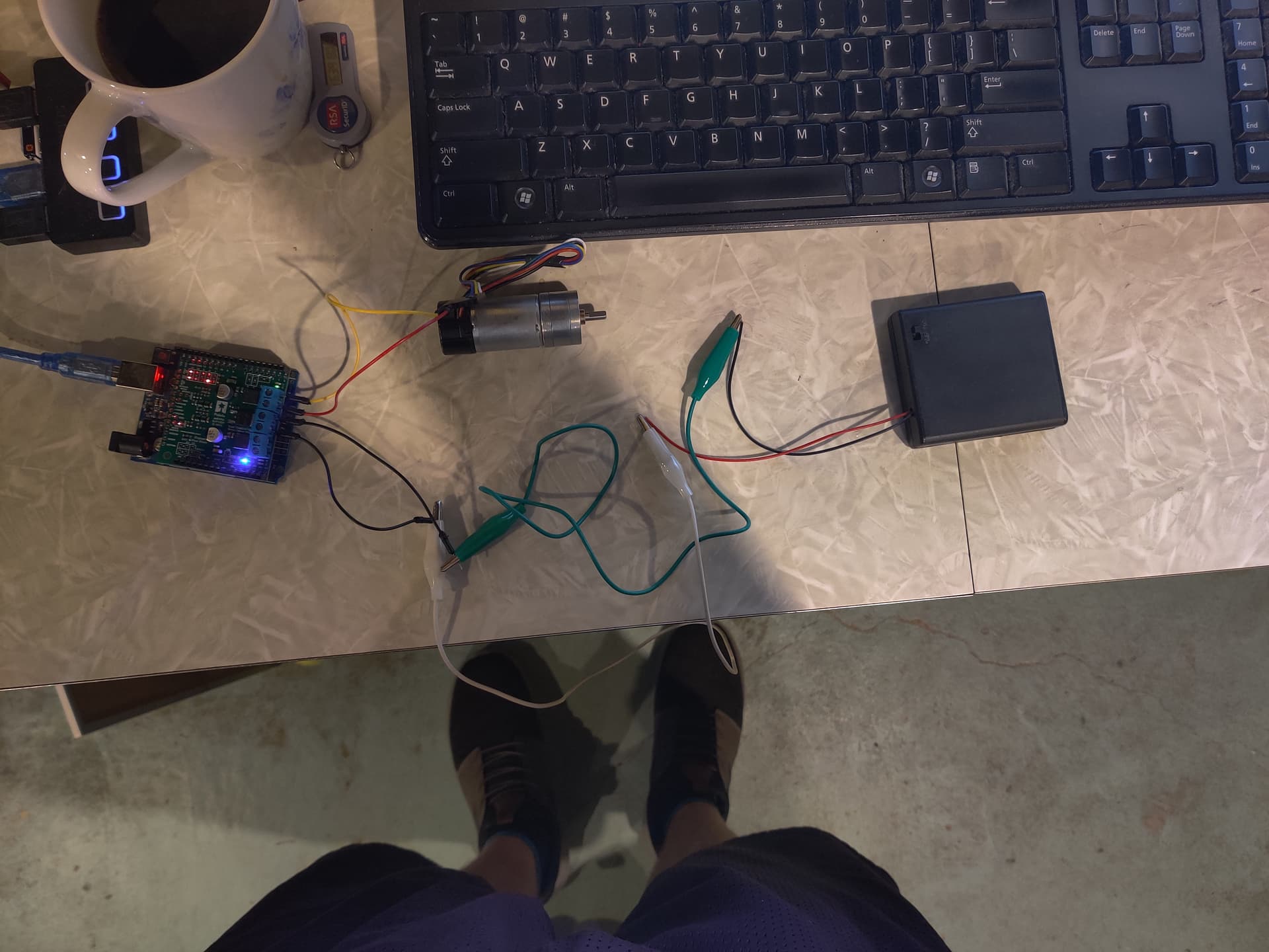
My last concern is power supply. I am using 4 Duracell AA batteries connected in series, which total 6 volts and a capacity of 1170 mAH. Not sure how much current it would be able to drive at a given instance, or if that would be enough. I know if I hook this power source directly to the motor, the motor does rotate. Is this an acceptable power source to be used with the shield in this power mode?
Yes, it should be fine to use your driver with only one of the channels connected to your motor. As a basic check, I suggest you also try just running the example program with no motors connected and verify that the indicator LEDs respond as expected.
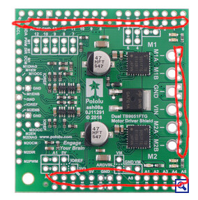
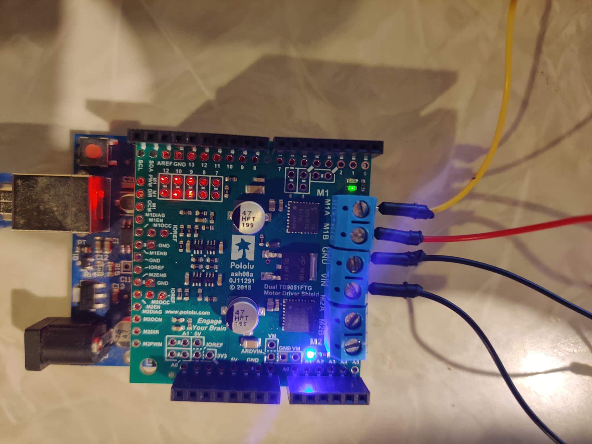
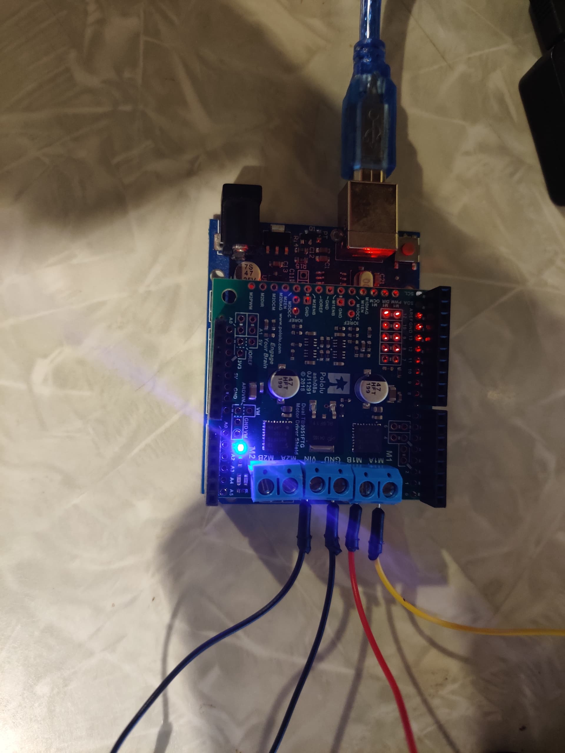
Doing a continuity test like you described is a good sanity check, but it is possible for a bad solder joint (or even sometimes a unsoldered pin) to sometimes pass a continuity test even though it is not really an adequate connection. With that in mind, can you post some pictures of your actual board that show all of the soldered connections so I can double check it? Some pictures of your overall setup that show all of your connections might also be useful to check for other problems.
Powering your shield like you proposed should be okay (at least for basic testing) as long as your batteries are charged and can handle the current draw of your motor, so you might double check that. Can you post a datasheet or specifications for your motor?
The solder joints on the terminal block pins look like cold joints, and they are probably not wetting to the board very well. It looks like not enough heat was applied; since those are larger pins and larger pads on the board, they take more heat than the smaller 0.1" pins. I suggest reworking those pins before trying to troubleshoot anything else.
If that does not make the issue go away, please post updated pictures of that. Can you also try commenting out the two while(1); lines in the stopIfFault() function from our example program and let me know what happens? Do you have any other power supplies that you can test your motor and driver with?
You can hear a strange buzzing as I’m guessing the program applies more current to the motor.
I was able to switch the power supply off and on during the running of the program and the motor did move. I was not able to replicate this behavior consistently though.
Don’t have any other power supplies. Was thinking about trying this one but I don’t think it will make a difference.
Took a look at the end of section 3c in the guide. Do you think this is something I should be considering?
Occasionally, electrical noise from a motor can interfere with the rest of the system. This can depend on a number of factors, including the power supply, system wiring, and the quality of the motor. If you notice parts of your system behaving strangely when the motor is active, first double-check that your power supply is adequate, then consider taking the following steps to decrease the impact of motor-induced electrical noise on the rest of your system:
Motor with one 0.1 uF capacitor soldered across its terminals.
Motor with two 0.1 uF capacitors soldered from its terminals to its case.
Solder a 0.1 µF ceramic capacitor across the terminals of your motors, or solder one capacitor from each terminal to the motor case (see the pictures to the right). For the greatest noise suppression, you can use three capacitors per motor (one across the terminals and one from each terminal to the case).
Make your motor leads as thick and as short as possible, and twist them around each other. It is also beneficial to do this with your power supply leads.
Route your motor and power leads away from your logic connections if possible.
Place decoupling capacitors (also known as “bypass capacitors”) across power and ground near any electronics you want to isolate from noise. These can typically range from 10 uF to a few hundred uF.
UPDATE 1
Tried a nominal 100nF cap (63.7nF based on my multimeter reading), and still not luck.
UPDATE 2
Tried running this
void stopIfFault()
{
  if (md.getM1Fault())
  {
    Serial.println("M1 fault");
    //while (1);
  }
  //if (md.getM2Fault())
  //{
  //  Serial.println("M2 fault");
  //  while (1);
  //}
}


void loop()
{
  md.enableDrivers();
  delay(1); // wait for drivers to be enabled so fault pins are no longer low

    md.setM1Speed(400);
    while(1)
    {
        stopIfFault();
    }
}
The soldering looks good now, although the noise in your video is concerning. Is the noise coming from the motor or the driver, and do you get the same behavior if you connect the motor to channel 2 instead of channel 1?
Given the results so far, it will be critical to get a better assessment of your power supply. Is there any way you can test your system with a more substantial supply, ideally something like an adjustable benchtop supply? (Maybe you could borrow one from a friend or access one at a community makerspace.) Maybe even just switching from alkaline batteries to some rechargeable NiMH batteries could produce different results. It would also be helpful if you could monitor your supply voltage. The ideal tool for that would be to use an oscilloscope if you can access one, but even checking it with a multimeter will be useful.
By the way, I would not recommend switching your system off when the motor and program are running since your Arduino will continue to send signals to the driver while it is unpowered. It would be better to include some extra peripheral in your system, like a button, that you can use to turn the motor on and off.
Is the noise coming from the motor or the driver?
Motor
Do you get the same behavior if you connect the motor to channel 2 instead of channel 1?
More or less. I was not consistently able to get the motor moving. I was able to get it spinning with 400 speed a few times. I recall loading the program with 400, the motor spun, then loading the program with 350, motor stopped spinning and buzzed, then reloading 400 and motor still buzzed.
It seems like I can load the program for 400, then take the motor pins off the motor terminals, then plug them back in while power is applied to the shield, and the motor will begin moving. I am hoping I am not damaging anything in this configuration. I was able to do this on motor1 as well I believe. Though this is far from ideal and only works for 400 as far as I can tell.
It would also be helpful if you could monitor your supply voltage. The ideal tool for that would be to use an oscilloscope if you can access one, but even checking it with a multimeter will be useful.
I can look into some of the more expensive tools you mention, but I don’t have them immediately available. I can give you the multimeter reading.
For motor2, it looks like when motor is hooked to shield, you get 4.18V across the power supply. When the motor is removed, that goes to 5.23V. For motor1, you get 4.22V across the power supply when motor1 is connected. That number becomes 5.32V when not connected.
Should I collect current readings for these setups or is that enough info to take another step/confidently recommend a different power supply? Wish I had a variable DC power supply, but that simply isn’t available.
The minimum operating voltage for the TB9051FTG is 4.5V, so if you can see your supply voltage dropping to around 4.2V with a multimeter, then it definitely seems like your supply is inadequate.
If you want to continue using AA batteries, I would suggest getting a pack that carries more cells. You could probably go up to 6 cells (nominally 9V alkaline or 7.2V rechargeable) and still be fine, though you might want to consider limiting the maximum duty cycle such that you never exceed an average applied voltage around that value (especially if you want to use more than 6 cells). For example, if you use a pack with 6 AA alkaline batteries, which would yield a nominal voltage around 9V, you might want to limit the maximum duty cycle to 67% (which corresponds to a speed value of 267 in our library).
Also, as I mentioned before, I suspect you might see different results just by switching to rechargeable NiMH batteries, though I think you will still need more cells in your system for it to work reliably.