I search a solution to operate the following system.
I do not find a connexion drawing to validate my assembly, which does not work.
Please, can you help me for the building.
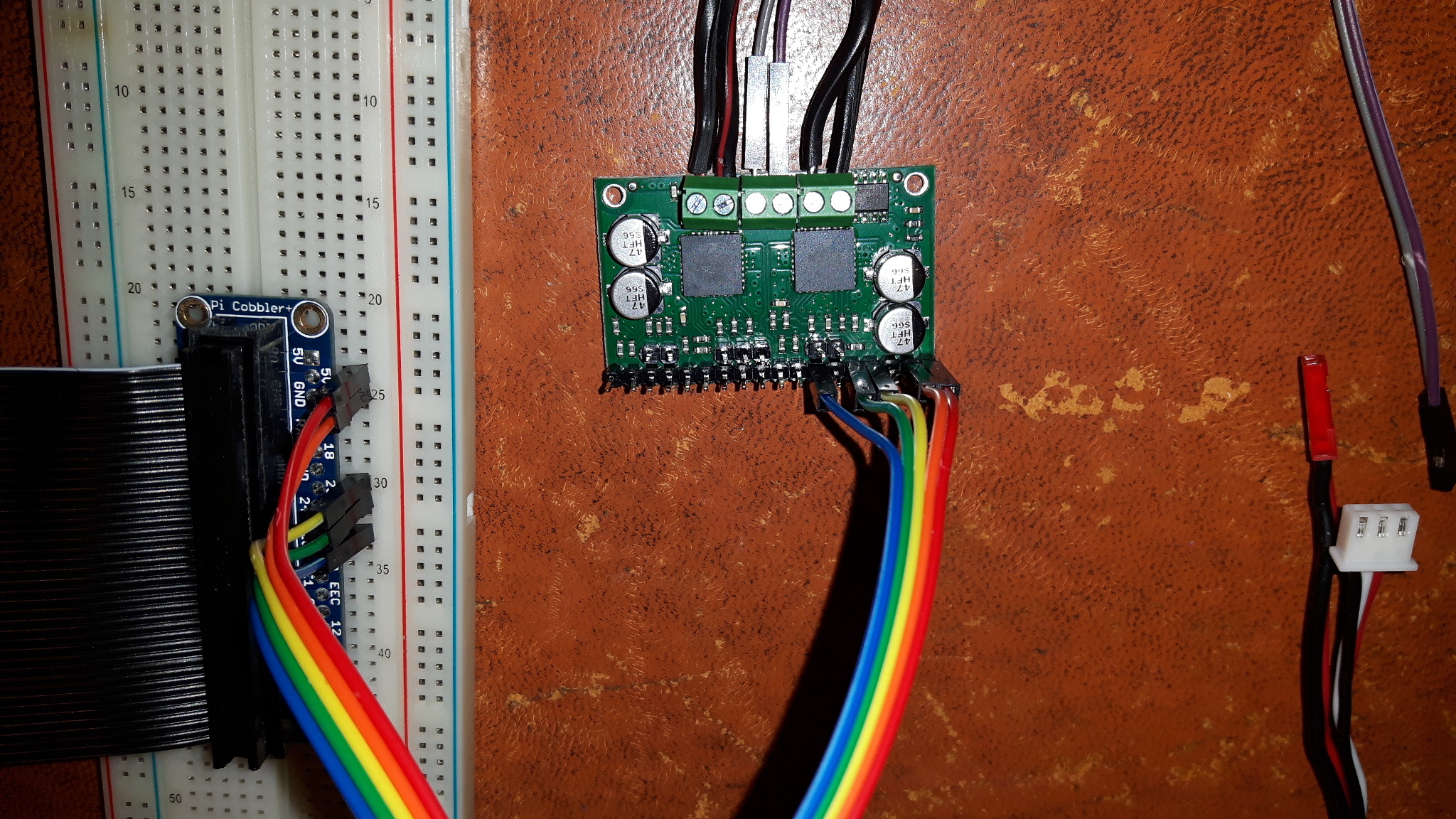
I got a motor driver to control two motors 12V 2A from my raspberry Pi 3. I wish to order these engines in pwm.
First I assembled the motor driver, then I realized a structure for the motors. If I concentrate on a single motor at first, I connect the pins 23 and 24 of the raspberry to the input M1IN1 and M1IN2 of the motor driver for the control. And the pin 25 to the input M1D1 for the variation in pwm.
the gnd of rasberry to the gnd of the motor driver and 5V of the rasberry to Vin of the motor driver.
Could post the code you are using? You mentioned connecting the Raspberry Pi’s 5V power line to the VIN pin of the MC33926. You should not. The VIN pins on both sides of the MC33926 are internally connected, so it seems like you were likely connecting your battery voltage directly to 5V from the Raspberry Pi, which could damage either the Pi or the driver.
1. import RPi.GPIO as GPIO
2. from time import sleep

3. GPIO.setmode(GPIO.BOARD)   ##je prefere la numerotation BOARD plutot que BCM

4. Moteur1A = 16      ## premiere sortie du premier moteur, pin 16
5. Moteur1B = 18      ## deuxieme sortie de premier moteur, pin 18
6. Moteur1E = 22      ## enable du premier moteur, pin 22

7. GPIO.setup(Moteur1A,GPIO.OUT)  ## ces trois pins du Raspberry Pi sont des sorties
8. GPIO.setup(Moteur1B,GPIO.OUT)
9. GPIO.setup(Moteur1E,GPIO.OUT)

10. pwm = GPIO.PWM(Moteur1E,50)   ## pwm de la pin 22 a une frequence de 50 Hz
11. pwm.start(100)   ## on commemnce avec un rapport cyclique de 100%


12. print "Rotation sens direct, vitesse maximale (rapport cyclique 100%)"
13. GPIO.output(Moteur1A,GPIO.HIGH)
14. GPIO.output(Moteur1B,GPIO.LOW)
15. GPIO.output(Moteur1E,GPIO.HIGH)

16. sleep(5)  ## on laisse tourner le moteur 5 secondes avec des parametres

17. pwm.ChangeDutyCycle(50)  ## modification du rapport cyclique a 50%

18. print "Rotation sens direct, au ralenti (rapport cyclique 50%)"

19. sleep(5)

20. print "Rotation sens inverse, au ralenti (rapport cyclique 50%)"
21. GPIO.output(Moteur1A,GPIO.LOW)
22. GPIO.output(Moteur1B,GPIO.HIGH)

23. sleep(5)

24. pwm.ChangeDutyCycle(100)
25. print"Rotation sens inverse, vitesse maximale (rapport cyclique 100%)"
26. sleep(5)


27. print "Arret du moteur"
28. GPIO.output(Moteur1E,GPIO.LOW)

29. pwm.stop()    ## interruption du pwm

30. GPIO.cleanup()
If I connect only M1in1, M1in2 and M1D1, it doesn’t work.
It looks like you are using pins 16, 18, and 22 to control motor 1 in your code, but earlier you mentioned connecting to pins 23, 24, and 25. You should adjust either your code or connections so those match. Also, it is not clear exactly what pins on the MC33926 your code is referring to with Moteur1A, Moteur1B, and Moteur1E. The board has one enable pin that must be pulled high, but there are two additional disable pins for each motor, D1 and nD2, that must be pulled high and low respectively for the motor to run. One of those disable pins is generally where a PWM signal would be applied. You will also need to control both IN1 and IN2. I recommend looking at the pinout table and Basic Application Connections section of the dual MC33926 carrier’s product page for more information on connections and configuring the driver.
You might consider using our Dual MC33926 Motor Driver for Raspberry Pi instead of the carrier you have, since it is made to plug directly into a Raspberry Pi and we have a library for it that makes it a lot easier for you to get started.
The code use the BCM code et my connecting the board code, but the pins are the sames, I am sorry for that confusion.
I have find the table on data sheet, the 5v is EN and the ground is D1 when nD2 is PWM signal.
IT’S WORK !
Concerning the dual MC33926 for raspberry, I dont want use it because it’s big.