Hi,
Please excuse my lack of electronics knowledge.
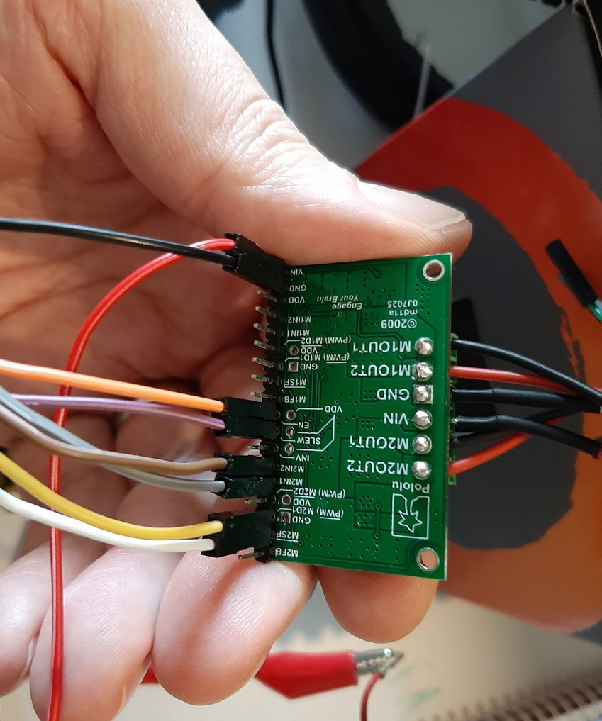
I’ve wired up my MC33926 motor controller to a Pi Zero W, The linked library from the product page I purchased it was actually for the RPI HAT version however the only difference seems to be two logic pins to control reverse or forward operation instead of 1 toggle pin.
I wrote up some software to control the MC33926 as per the logic truth table in the official doc.
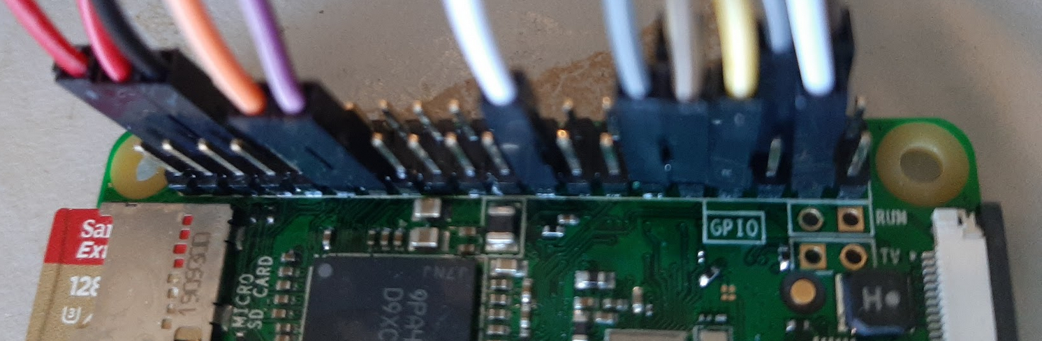
I’m not a pro at soldering so checked all the RPI pin connections to the breadboard are indeed high or low based on my wiringpi commands in the Python interactive interpreter I can also see some voltage blipping on the PWM pin when it should be sending voltage.
The displayed pin status using the wiring pi CLI tool gpio readall indicates the RPI thinks its pins are doing as my python app is telling it to.
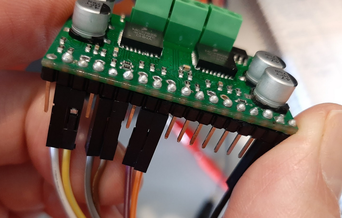
I must admit I’ve had to resolder a few pins as when pushing the MC33926 into the bread board they popped out. However I did this on the Pi Zero’s pins also and every time I’ve tested the ones in use they show voltage on logic 1 and - or none on logic 0 as expected, same as PWM. Although without further options I think ditching the breadboard and re-re-soldering /re-assembling a lot gentler will be the option.
the SF pin is on HIGH during the app running, Which if its connected properly is meant to indicate no fault.
I wrote a little one liner to monitor changes to the pins every second and it shows that the logic is being set matching the truth table;
slew pin: high
enable pin: high
IN1, IN2: high/low respectively
PWM/D2: high/low depending on when reading pin.
It then appears to show how PWM would look with my 1 second sleep on the CLI tool, With voltage showing 0 then 1
Does anyone have any tips, Maybe how I might use a multi-meter to tell if I melted the motor controller when I was soldering like a noob?
In case your interested this is the two liner its not perfect.:
alias rall="gpio -g readall | grep -P '{|5|6|26|28|27|23|25|24|Physical|}'"
touch current.txt; while true; do rall > new.txt; diff current.txt new.txt; mv new.txt current.txt;sleep 1;  done
Part of the output as the Python code runs.
>  | BCM | wPi |   Name  | Mode | V | Physical | V | Mode | Name    | wPi | BCM |
>  |     |     |    3.3v |      |   |  1 || 2  |   |      | 5v      |     |     |
>  |   2 |   8 |   SDA.1 | ALT0 | 1 |  3 || 4  |   |      | 5v      |     |     |
>  |   3 |   9 |   SCL.1 | ALT0 | 1 |  5 || 6  |   |      | 0v      |     |     |
>  |   4 |   7 | GPIO. 7 |   IN | 1 |  7 || 8  | 0 | IN   | TxD     | 15  | 14  |
>  |     |     |      0v |      |   |  9 || 10 | 1 | IN   | RxD     | 16  | 15  |
>  |  27 |   2 | GPIO. 2 |  OUT | 1 | 13 || 14 |   |      | 0v      |     |     |
>  |  22 |   3 | GPIO. 3 |  OUT | 1 | 15 || 16 | 0 | IN   | GPIO. 4 | 4   | 23  |
>  |     |     |    3.3v |      |   | 17 || 18 | 1 | OUT  | GPIO. 5 | 5   | 24  |
>  |   9 |  13 |    MISO |   IN | 0 | 21 || 22 | 0 | OUT  | GPIO. 6 | 6   | 25  |
>  |  11 |  14 |    SCLK |   IN | 0 | 23 || 24 | 1 | IN   | CE0     | 10  | 8   |
>  |     |     |      0v |      |   | 25 || 26 | 1 | IN   | CE1     | 11  | 7   |
>  |   0 |  30 |   SDA.0 |   IN | 1 | 27 || 28 | 1 | IN   | SCL.0   | 31  | 1   |
>  |   5 |  21 | GPIO.21 |  OUT | 0 | 29 || 30 |   |      | 0v      |     |     |
>  |   6 |  22 | GPIO.22 |   IN | 1 | 31 || 32 | 0 | ALT0 | GPIO.26 | 26  | 12  |
>  |  13 |  23 | GPIO.23 | ALT0 | 0 | 33 || 34 |   |      | 0v      |     |     |
>  |  19 |  24 | GPIO.24 |  OUT | 0 | 35 || 36 | 0 | OUT  | GPIO.27 | 27  | 16  |
>  |  26 |  25 | GPIO.25 |  OUT | 1 | 37 || 38 | 1 | OUT  | GPIO.28 | 28  | 20  |
>  | BCM | wPi |   Name  | Mode | V | Physical | V | Mode | Name    | wPi | BCM |
14,15c14,15
<  |   5 |  21 | GPIO.21 |  OUT | 0 | 29 || 30 |   |      | 0v      |     |     |
<  |   6 |  22 | GPIO.22 |   IN | 1 | 31 || 32 | 0 | ALT0 | GPIO.26 | 26  | 12  |
---
>  |   5 |  21 | GPIO.21 |  OUT | 1 | 29 || 30 |   |      | 0v      |     |     |
>  |   6 |  22 | GPIO.22 |   IN | 1 | 31 || 32 | 1 | ALT0 | GPIO.26 | 26  | 12  |
17,18c17,18
<  |  19 |  24 | GPIO.24 |  OUT | 0 | 35 || 36 | 0 | OUT  | GPIO.27 | 27  | 16  |
<  |  26 |  25 | GPIO.25 |  OUT | 1 | 37 || 38 | 1 | OUT  | GPIO.28 | 28  | 20  |
---
>  |  19 |  24 | GPIO.24 |  OUT | 1 | 35 || 36 | 0 | OUT  | GPIO.27 | 27  | 16  |
>  |  26 |  25 | GPIO.25 |  OUT | 0 | 37 || 38 | 1 | OUT  | GPIO.28 | 28  | 20  |
15c15
<  |   6 |  22 | GPIO.22 |   IN | 1 | 31 || 32 | 1 | ALT0 | GPIO.26 | 26  | 12  |
---
>  |   6 |  22 | GPIO.22 |   IN | 1 | 31 || 32 | 0 | ALT0 | GPIO.26 | 26  | 12  |
17,18c17,18
<  |  19 |  24 | GPIO.24 |  OUT | 1 | 35 || 36 | 0 | OUT  | GPIO.27 | 27  | 16  |
<  |  26 |  25 | GPIO.25 |  OUT | 0 | 37 || 38 | 1 | OUT  | GPIO.28 | 28  | 20  |
---
>  |  19 |  24 | GPIO.24 |  OUT | 1 | 35 || 36 | 1 | OUT  | GPIO.27 | 27  | 16  |
>  |  26 |  25 | GPIO.25 |  OUT | 0 | 37 || 38 | 0 | OUT  | GPIO.28 | 28  | 20  |
16c16
<  |  13 |  23 | GPIO.23 | ALT0 | 0 | 33 || 34 |   |      | 0v      |     |     |
---
>  |  13 |  23 | GPIO.23 | ALT0 | 1 | 33 || 34 |   |      | 0v      |     |     |
16c16
<  |  13 |  23 | GPIO.23 | ALT0 | 1 | 33 || 34 |   |      | 0v      |     |     |
---
>  |  13 |  23 | GPIO.23 | ALT0 | 0 | 33 || 34 |   |      | 0v      |     |     |
16c16
<  |  13 |  23 | GPIO.23 | ALT0 | 0 | 33 || 34 |   |      | 0v      |     |     |
---
>  |  13 |  23 | GPIO.23 | ALT0 | 1 | 33 || 34 |   |      | 0v      |     |     |
16c16
<  |  13 |  23 | GPIO.23 | ALT0 | 1 | 33 || 34 |   |      | 0v      |     |     |
---
>  |  13 |  23 | GPIO.23 | ALT0 | 0 | 33 || 34 |   |      | 0v      |     |     |
14c14
<  |   5 |  21 | GPIO.21 |  OUT | 1 | 29 || 30 |   |      | 0v      |     |     |
---
>  |   5 |  21 | GPIO.21 |  OUT | 0 | 29 || 30 |   |      | 0v      |     |     |
14c14
<  |   5 |  21 | GPIO.21 |  OUT | 0 | 29 || 30 |   |      | 0v      |     |     |
---
>  |   5 |  21 | GPIO.21 |  OUT | 1 | 29 || 30 |   |      | 0v      |     |     |
Here is the associated python code:
import wiringpi
from time import sleep


class Motor:
    def __init__(self,
                 pwm_pin: int,
                 forward_pin: int,
                 reverse_pin,
                 en_pin: int = 5,
                 slew_pin: int = 22,
                 sf_pin: int = 10
                 ):
        self.pwm_pin = pwm_pin
        self.forward_pin = forward_pin
        self.reverse_pin = reverse_pin
        self.en_pin = en_pin
        self.slew_pin = slew_pin
        self.sf_pin = sf_pin
        self.max_speed = 480
        wiringpi.wiringPiSetupGpio()
        wiringpi.pwmSetMode(wiringpi.GPIO.PWM_MODE_MS)
        wiringpi.pwmSetRange(self.max_speed)
        wiringpi.pwmSetClock(2)
        wiringpi.pinMode(self.pwm_pin, wiringpi.GPIO.PWM_OUTPUT)
        wiringpi.pinMode(self.forward_pin, wiringpi.GPIO.OUTPUT)
        wiringpi.pinMode(self.reverse_pin, wiringpi.GPIO.OUTPUT)
        wiringpi.pinMode(self.en_pin, wiringpi.GPIO.OUTPUT)
        wiringpi.pinMode(self.slew_pin, wiringpi.GPIO.OUTPUT)
        wiringpi.pinMode(self.sf_pin, wiringpi.GPIO.INPUT)

    def enable(self):
        wiringpi.digitalWrite(self.en_pin, 1)

    def disable(self):
        wiringpi.digitalWrite(self.en_pin, 0)

    def move(self, direction: int, speed: int = 200):
        if speed > self.max_speed:
            speed = self.max_speed
        if direction is 1:
            print('Attempting to move forward')
            self.enable()
            wiringpi.digitalWrite(self.slew_pin, 1)
            wiringpi.digitalWrite(self.reverse_pin, 0)
            wiringpi.digitalWrite(self.forward_pin, 1)
            print(f'Sending PWM to pin {self.pwm_pin}')
            wiringpi.pwmWrite(self.pwm_pin, speed)
            sleep(10)
            self.disable()
            print(f'Switching off PWM to pin {self.pwm_pin}')
            wiringpi.pwmWrite(self.pwm_pin, 0)
        elif direction is 0:
            print('Attempting to move reverse')
            self.enable()
            wiringpi.digitalWrite(self.slew_pin, 1)
            wiringpi.digitalWrite(self.forward_pin, 0)
            wiringpi.digitalWrite(self.reverse_pin, 1)
            print(f'Sending PWM to pin {self.pwm_pin}')
            wiringpi.pwmWrite(self.pwm_pin, speed)
            sleep(10)
            self.disable()
            print(f'Switching off PWM to pin {self.pwm_pin}')
            wiringpi.pwmWrite(self.pwm_pin, 0)


motor0 = Motor(12, 19, 26)
motor1 = Motor(13, 16, 20)

motor0.move(1)
motor1.move(1)
sleep(5)
motor0.move(0)
motor1.move(0)
print('Finished')