DSM44 servo failure

Hello Derrill

Thank you for your feedback

I’m using DSM44 for quite fast and intensive movement, but not with constant load, rather fragmentary with different intervals of time between activation and activation for rest, maximal activation period is one minute, rest can be 2 minutes. It is not very wide angle of degree 160-430 is maximum, mostly much less 160-190, short and fast movement about 2-3 messages per second, mechanical mass acceleration 50-200 grams, broken one was with minimal load. It newer goes against own limit or any external limit in assembly, in mechanics I’m using anti-limit heads instead of horns, which is able to allow servo freely turn around own axis in case of unexpected angle, for example with some electricity failure, there is no weight or pressure on it.

I think the wires used in particular device are very fragile, as I’ve already said, I was reached a short-circuit with another DSM44 servo by this reason, at that time I managed to fix it, motor still works

I’m not sure about how many movements broken motor did before fail, but I think not enough, to say many, also because this part of mechanism was added later than others, so this motor is newer compared to other

Without having some idea of how many cycles the servo performed and what kind of load it was under, it is difficult to say whether or not the failure was simply due to the wear or something else.

Typically, it would not be surprising for a hobby micro servo like that to fail over a 5 month period of intermittent intense use.

-Derrill

Well, as I have said above the load is minimal, but now I’m sure, this device not works well, or I just get defective motors from pololu, because another DSM44 motor failed, which load was extremely minimal, it simply turns own plastic horn in fact almost without anything on it, using period 10 minutes, turn from side to side with 10 seconds rest interval, i just took it out of the box, ordered 10 May 2019 from pololu, the same thing happened to it

Previously I have checked all pins on Arduino controller and servo shield with 1000uF capacitor for 8 motors which is 6 DSM44 and 2 FEETECH Mini Servo FT1117M

I’m not sure if hobby means immediately broken, I bought this motors because it is fast and quite powerful by given description, with a lot supply of weight in relation to my load, which maximum is 150 grams

It is very difficult and expensive to me send motors back, because I am very far from US. Can you give me some useful guide for checking and repairing at home, what to check and how to fix, at least I want to figure out what exactly happened to these two motors, what exactly is the defect, and could I somehow fix it. The motor main gear just does not reacts to command, there was no smoke, I can’t see anything melted inside on IC or in contact between wires

Maybe you can advice me some more reliable servo about the same size, which should be same fast 6V: 0.07 sec/60° and torque no less 1.6 kg cm because in project I need it intensive with supply for weight load maximum 200 grams

Hello,

It is probably not practical to repair a broken servo since parts are not likely to be readily available locally and they could be broken in a number of ways.

Having broken another servo makes it seem like something is not as simple in your setup as you believe. Can you take the newer servo apart to see how what part failed (e.g. did one of the gears break, is it a motor issue, etc)? Could you post a video of your setup showing how you’re using the servo?

-Derrill

Here is (new, arrived to me yesterday, my order) broken servo place replaced by older working one to show you movement, which goes by +1 increment, it is very slow and never jumps abruptly through steps, no load and no limit against movement, just moves two eyeballs from one side to another, mechanism is quite small and moves very easily, without a motor, the mechanism literally moves from position to position simply even from a slight inclination of the part to the side

and here is more intensive part, where another motor was broken, which is eyelids, mechanism is also very soft and easy moved, but movement is much faster to open and close eyelids, sometime 3 times sequentially, 2-3 messages per second, to do fast multiple blinking, in this case from position to position for example from 160 to 430. Nothing comes into contact with anything to block each other in mechanism during process, it is completely checked. Below shown arm glued with original hardware. Weight of eyelids, moving arm, rod, servo arm, and own hardware including is 56 grams.

So it is absolutely different intensiveness, movement and different pins (other pins also checked for both as damaged as well as for working servos, if assume that the problem came from the controller), but the damage result with motors is same

As you can see even if the motor will rotate for 360 degrees for some unexpected reason, it will not reaches limit, but just will go freely in the opposite direction in both example as eyeballs from side to side and eyelids open-close, it is provided for all moving elements in the mechanism

What about broken servos, I can’t find anything what looks broken, melted, disconnected, or incorrectly connected inside, gear turns by turning main gear manually well, and it produces some slight noise with touching by finger when it is connected to the shield, but does not turns with command, V+ and Gnd shows the same as described above

this is problem, because now I have to order 2 new motors at once, and wait again until the devices will be delivered to the opposite side of the planet, what requires about a week, but I’m not sure if it will work, it may be necessary to change the mechanism for other servos and print everything again, also it is not too easy to find such small, fast and powerful motors. All this setup was done with different motors, which was never broken, but was slower, weaker torque and plastic gear, that’s why I have changed everything for DSM44

Your eye mechanism looks really cool!

It sounds like the servo control electronics might have been damaged somehow. One way you could verify this is by disconnecting the motor inside the servo from the control board and seeing if it and the gearbox work as expected when powered directly.

If the electronics are damaged, that would almost certainly be caused by exposure to conditions beyond what it is rated for. Some power supplies can have unpredictable or ugly start-up characteristics when first turned on, with the voltage spiking well above the set point or sometimes even going negative. Do you ever turn your power supply on while the servos are connected? If so, can you measure your power supply with an oscilloscope to see if there are any odd voltage spikes on power-up? Also, can you measure the output to be sure it is 6V as expected?

Another possible explanation could be sending the servo signals while it is unpowered. Is there the potential for this in your setup?

Also, can you post your code?

-Derrill

Thank you!

I’ve designed this for small size anthropomorphic animatronic robot project, mechanism implements control of X, Y and eyelids, complete assembly uses 6 DSM44 and 2 FT1117M servos. Once I’ve posted question about hardware Suitable metal horn for DSM44 with 20T 3.5mm and FT1117M 25T 6mm servo gear, but in the end I’ve solved this problem by gluing of original hardware with 3D printed arm as shown above

I’ve checked both with direct powering, seems like motors are dead. So I’ve ordered 2 new units of DSM44, I don’t want to change the whole mechanism for other motors yet

Please correct me if i get it wrong, you mean, if I have ever plug power supply to electrical outlet while it is connected to shield with servos. If so, usually I plug adapter to electrical outlet first, then plug jack to shield, so each time I plug power jack to device, servos are connected, when adapter is already on, but I do not rule out that at some point this did not happen, even this tester shows 6.426 V, oscilloscope not shows anomalies with plug to electrical outlet and after

Once again, if I get it correct, if I ever send signals via USB to controller, or from Arduino controller sketch with process or turn on for example, when shield with servos unpowered from power adapter? If so, yes, it is possible, because sketch setup() sets number of default positions for motors with plug of USB to computer and turning on, not excluded that at some point, I’ve connected controller without having connected the adapter

Another thing that symptomatically corresponds to this reason, both times I found the motor in malfunction with starting of new session immediately after connecting, it did not happened during the process. Seems like I have to monitor power to avoid setup() commands, or any other signals during process in case if shield is not powered with adapter.

Could you explain me a little on this, please, how it influences motor and what is a best way to avoid such condition automatically, even if need to send signals with controller turn on exist and necessary, but adapter is not connected to shield first accidentally.

If this is the reason, this is what I think to do according Arduino forum advice, please check if i am on the right track:

The voltage divider consisting of the resistors will divide the 6V to 5V for the controller digital input. The values should not be a critical, can be made higher, but maintain the relationship to still get the 5V. The diode will prevent current to flow from the shield into the voltage divider, when the shield is powered through other means. Now I can do a digitalRead(pin) on the digital input pin to check, if the power was applied:

Nbde6

simulation of this circuit

Another advice offers monitor power to the servos using one of analog pins analogRead(pin), seems like depending, on if you need a simple yes no result or the specific voltage level, but I do not have enough experience here to be sure which of the options is more suitable and what is the difference for particular case. As it was explained in case of using normal power adapter, which means, that the 6V for the shield are already regulated beforehand. In this case there are only two possibilities, 6V or no voltage at all, then the digital pin should be sufficient. In case of battery connected there and want to also sense the low voltage case, I can use an analog pin

Here is other found close guides:

  1. Measuring DC Voltage using Arduino
  2. Arduino Battery Voltage Indicator
  3. Arduino energy meter

Controller code only receives value pwm.setPWM(1, 0, Serial.parseInt()); with separate condition for each motor from desktop control application different ways, PWM frequency pwm.setPWMFreq(60);. It never goes out of min-max range, previously found for particular servo, defined in controller sketch as 160-500, and even more limited for each process in main output code in range of 170 to 430. But as I noted above there is setup() with “turning on” positions

I’m surprised that the motor is the damaged part, so I just want to make sure your direct test was valid. Did you physically disconnect the motors from the control electronics before trying to apply power, and did you make sure the motor wasn’t being blocked by a jammed gearbox?

If the motor is the part that failed, I think it is much less likely that the failure was caused by a spike from your power supply or sending logic signals when the servo was not powered. However, these are still generally situations that it is good practice to avoid.

To answer your questions, if you have looked at the way the output voltage rises when you plug in your supply and did not see any large spikes, it is probably okay. If you send signals from your controller while the servo itself is not powered, the servo’s built-in control board could try to partially power itself through the signal input pins which could damage it. (This is generally true of electronics like this, so we recommend avoiding it.) You could read the servo power voltage with a divider like you mentioned to try to detect when the servo is not powered, or you could just make sure that the servo is never plugged into your controller when power is not on.

Unfortunately, at this point it is not clear to me what might have damaged your servos. Please let us know how it goes with the replacements.

-Derrill

Here is a principal way, how I’ve checked motor, of course with a more accurate connection, rather than just pressing it with fingers as shown. Disconnected from the control electronics:

60724392_371517187044420_8696275001541656576_n

I’ve tried directly from adapter, as well as from the controller. If motor is in a good condition, even this way, it should have work. Motor from damaged DSM44 does not turns. I’ve checked different working motor same way, and it works.

Gears turns well manually, it doesn’t seem like something might get stuck there:

As I’ve said above, once was a shorting in contact between S, V+, G wires. Problem was solved with using of varnish where the wires are soldered with control electronics. Shorting was manifested with disconnecting of USB and keeping power adapter connected to shield. All motors begin to move by itself out of control.

Shortly before the failure, sometime slight random movement (in this case not for all, but for one of motors) was also observed. If there is no other obvious reason, maybe, it is possible that such situation could damage the motor, I’m not sure. However, all motors that behaved in this way and then were varnished, still works

Power plug moment on hold and direct line after, on the right, voltage:

Thank you for that additional information. Can you measure the resistance across the motor terminals?

-Derrill

Broken motor 1, removed from control board, meter on 2000k Ω, without turning by hand:

VΩmA to red wire, COM to blue wire = 0

with turning by hand:

VΩmA to red wire, COM to blue wire = 570, 1165, 1319…

but not constantly, maybe my tester is not accurate enough, and same with damaged motor 2.

broken motor 1, again soldered with control board, in this case meter on 2000 Ohm:

VΩmA to V+, COM to Gnd = 1315
VΩmA to Gnd, COM to V+ = 610

broken motor 2:

VΩmA to V+, COM to Gnd = 1348
VΩmA to Gnd, COM to V+ = 606

One of working motors, meter on 2000 Ohm:

VΩmA to V+, COM to Gnd = 1292
VΩmA to Gnd, COM to V+ = 608

Also, I’m not sure why, but this value changes and goes down each time I touch wire with terminals, as well as I do not quite understand, what determines the difference between these results. As I said, possibly LCR meter is not accurate enough, or I’m doing something wrong way. If so, then please tell me what exactly I am doing incorrectly.

Can you post some pictures showing how you are measuring the resistance, including your meter display?

-Derrill

Soldered with board shows numbers from control electronics, and separated motor is zero with damaged motors, except mechanical manual turning as shown above. Measuring the resistance:

Those results seem consistent with failure of the brushes. Several things can cause this, but the most common one is wear from friction over the full lifetime of the servo.

Please let us know how your replacement servos seem to be working in your setup once you get them going.

-Derrill

I’ve bought a two new motors, but It seems it was a last DSM44 in stock. As I get it, Pololu did not updates immediately the product when it ends. I would like to get several units of this servo, if something happens again and I will be forced to use spare motors, also I don’t want to buy it from another source. I should have a demonstration of my robot in the near future, and I would like to have some guarantee in case of a malfunction

You’ve said there are number of reason resulting with failure of the brushes, so I’m trying to figure out somehow, what to do further, get more DSM44 or use something else, because, as I have said above, one of damaged motors was absolutely new. Could you list this reasons, please, what can cause this, and what is a “full lifetime”, how do you measure this?

PowerHD (the manufacturer), does not specify the use life of those servos, and ultimately the lifetime depends heavily on the actual application. My reference to the “full lifetime of the servo” was just regarding having the failure mode be wear from your particular application as opposed to some kind of sudden, catastrophic failure from exceeding what the servo can tolerate.

While those servos are currently out of stock, they can be backordered and will ship once we receive more. Unfortunately, we don’t have a good estimate right now for when that will be, but we should know more in a few days.

There is likely more than a single cause of failure for those two servos. Worn brushes would account for the damage to the old servo that lasted for about 5 months. Other causes like power spikes, improper power connections or ESD could have damaged the newer servo. There are likely other factors that could be causes, but speculating about all possible causes is probably not practical with the limited information we have.

-Derrill

Thank you for your attentive support

Finally I’ve received the motors, I’ve already added new servos to assembly. I hope it will work fine. Sometimes, very rarely, when the motors reached their position and stopped, I hear some very low crackling, click-like sound. I can say for sure, it is not a physical barrier, it is not any unexpected signal from the controller, it is not looks like short circuit, in most cases it does not happens, it happens from a hundred maybe just one time, as with same, also with different movement positions. I’m not sure, if it is a sign of something, what should alarm

One possibility that comes to mind is the gear teeth slipping due to high loads or hitting the end stop. Are you sure you are not sending signals beyond the physical range of the servo? The second FAQ under the FAQs tab of the servo’s product page talks about finding the limits of the servo’s range of movement.

-Derrill

Hello, Derrill

Sorry for very late replay to your last answer.

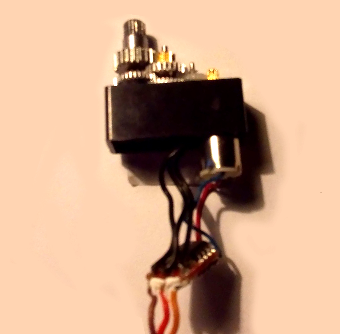
After number of successful testing with new DSM44, purchased almost half year ago this particular assembly was left for a while, device wasn’t used all this time.

Today I’ve tried to use it, but same hаppend very soon after number of sessions, one of the new servos went bad again.

Motor horn never reaches a physical limit anywhere in the assembly for sure, acceleration mass is small, mechanism moves very easily with no resistance or weight load.

SERVOMIN/MAX are defined with 160 to 500, furthermore serial event operates in narrower range

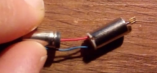
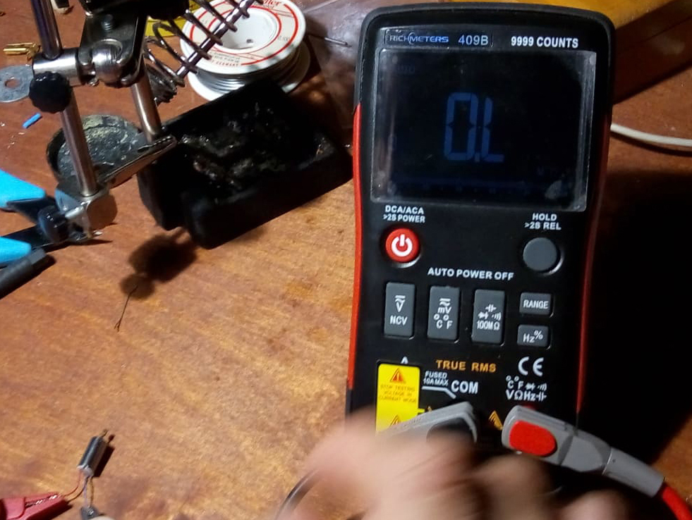
Something destroys motors, I have checked power wires of new damaged device, motor receives voltage, but motor does not moves anymore.

I’ve different project, which uses same devices (controller, same shield or driver, power adapter), and it was never happened with it.

DSM44 is small, fast, powerful, but by some unknown reason does not works for me, and I’m not sure how to find reason.

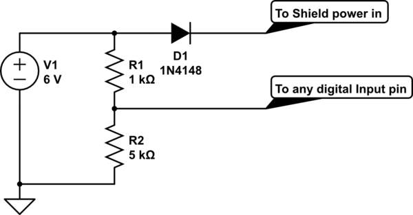
I can’t determine what the problem is with this 6V 8A power supply, but I almost sure that it happens when I plug power wire before plug of controller USB to PC, but checking of power plug moment does not shows any anomalies and controller setup() contains only: Serial.begin(9600); pwm.begin(); pwm.setPWMFreq(60); delay(10); in case of sending value to PWM first it goes through power divider condition, and this affects only DSM44.

I’m not sure how to check power supply other way and as I’ve said this same power supply works for another assembly with different motors. So, the only advice I’m trying to find now is a suitable device which will cover most of specifics required for my project:

  1. Speed: No less 0.07 sec/60° with 6V

  2. Power: Torque no less 1.5 kg cm with 6V

  3. It does not requires get feedback, as if I use smart servo, but must be digital, because degree position should operate in short ranges with high speed, so quick response, fast acceleration and accuracy is important

  4. Small size: from 20x9x26 or less to 35x12x30 plus/minus 1-5mm max

  5. Must be a quite, silent as much it is possible (less important since it is difficult find a servo motor without noise)

  6. Must be secure for not constant, but intense work processing of serial events

  7. Control method uses Arduino Uno or Due and Adafruit Servo Shield or Driver, 6V 8A power supply, sanding of PWM degree value via serial port from C# desktop application, so controller sketch contains only receiver conditional function per each unit

Here is some ideas, that I try to understand and figure out what could be the best choice in my case.

To find suitable servo is not easy, it must be fast, powerful, small and secure, DSM44 is only motor I found by size, speed and power, but it fails for me.

I’m not sure about Brush Servo Motor and Brushless difference with my requirements regarding safety, maybe I should use Brushless motors.

As variant if it is possible controlling of DC motors, I’m not sure about correct technique in this case, maybe I’ve to use somehow absolute of rotary encoder for this task, because in particular project gear fixing in position is not as important as start with initial position each time with controller setup() or desktop app load. If the pins are not fixed, I can move the parts manually, since in my mechanism suspended parts are controlled by horizontal shift, mobility is even good, but the loss of position after a reboot will lead to the loss of positions due incorrect start. In real world brushless DC able to control steps is a stepper motor, I’ve tried Stepper Motor: Bipolar, 200 Steps/Rev, 20×30mm, 3.9V, 0.6 A/Phase with A4988 driver , but it seems that the stepper is not quite suitable device for particular project by number of reasons, it is too big if enough powerful, it requires drivers, switch limits, which is extra in such small assembly space.

Arduino PID based DC motor position control system must be close to what I’m trying to get, but I can’t find out with correct motor by size, speed and power and suitable compact device to control multiple motors in assembly.

Another idea ClearPath Servo Motor in terms of quietness, however, the control method as available size of the motors is not entirely obvious to me yet.

Also I think about high voltage motor control if it can lead me to solution, which can be fast, powerful and quite. Maybe I have to use some professional device, if it is possible to find something not extremely expensive for personal project, but even so, I have not yet found anything suitable by described requirements and the simplicity of my assembly for this project, perhaps because my search is not correct enough, since I am more versed in programming and mechanics, than in electronics, moreover in motors

Any advice would be helpful

I do not have any specific suggestions for an alternative servo, but you might look into using a brushless servo like you mentioned if you can find one that small. Unfortunately, we do not carry brushless servos like that.

-Derrill