To just do a bench test of the motor drivers on the Romi bot using the power distribution board, I hooked up VREG (5V default) and GND to the power rails of a breadboard and then the SLP, DIR, and PWM pins for each motor directly to the 5V rail. The right motor works fine if I switch the three control pins back and forth between 5V and GND. However, the left motor will not change direction when I switch the DIR wire. It will coast when SLP goes low (it is pulled high on the board) and turn off when PWM is disconnected but there is not change in speed or direction if the DIR pin is on either rail or disconnected.
I noticed that the left motor driver chip is very close to the BAT2+ terminal on the distribution board. If I’m reading the specs correctly, the DVR8838 can handle only up to 260C for surface mount soldering. Is it possible while using a hand solder at above 260C that the chip could have been damaged? It is just strange that if this is the case, only the direction input was damaged?
I saw another post mention a software bug for direction control in the DRV8838 library but I’m not using any software at all. I also checked the soldering on the motor control header and it all looks good (i.e. the person soldering didn’t forget to solder that pin and it is nicely shaped like the others). I’m also confident in the jumper wire connection as I tried multiple new cables with the same results. I could try probing the traces but don’t have probes that are fine enough to just hit one pin easily and didn’t want to resort to attempting to scrape away solder mask until after asking.
Sorry you are having trouble with your Motor Driver and Power Distribution Board for Romi Chassis. It is possible to damage the DRV8838 with hand soldering, and that might affect only one channel. However, it does seem unlikely, so let’s troubleshoot to see if there is something else going on.
Did the left motor channel’s direction control ever work for you? What are you using for motor power? Could you post pictures of your test setup and your distribution board?
Thanks for getting back. Attached is a pic of the setup. Using the output of the Vreg (still configured as default 5V) for the positive rail and will get no change of direction if I swap the green wire connected to DIR from GND to 5V. Vm is still connected to the default after Vsw and using both battery banks so ~9V. Just to be extra sure, I used two different sets of cables as well with same results.
I did not ever see the DIR working for the left motor - I didn’t solder the bot (my boss did )and he is not sure if he saw it working.
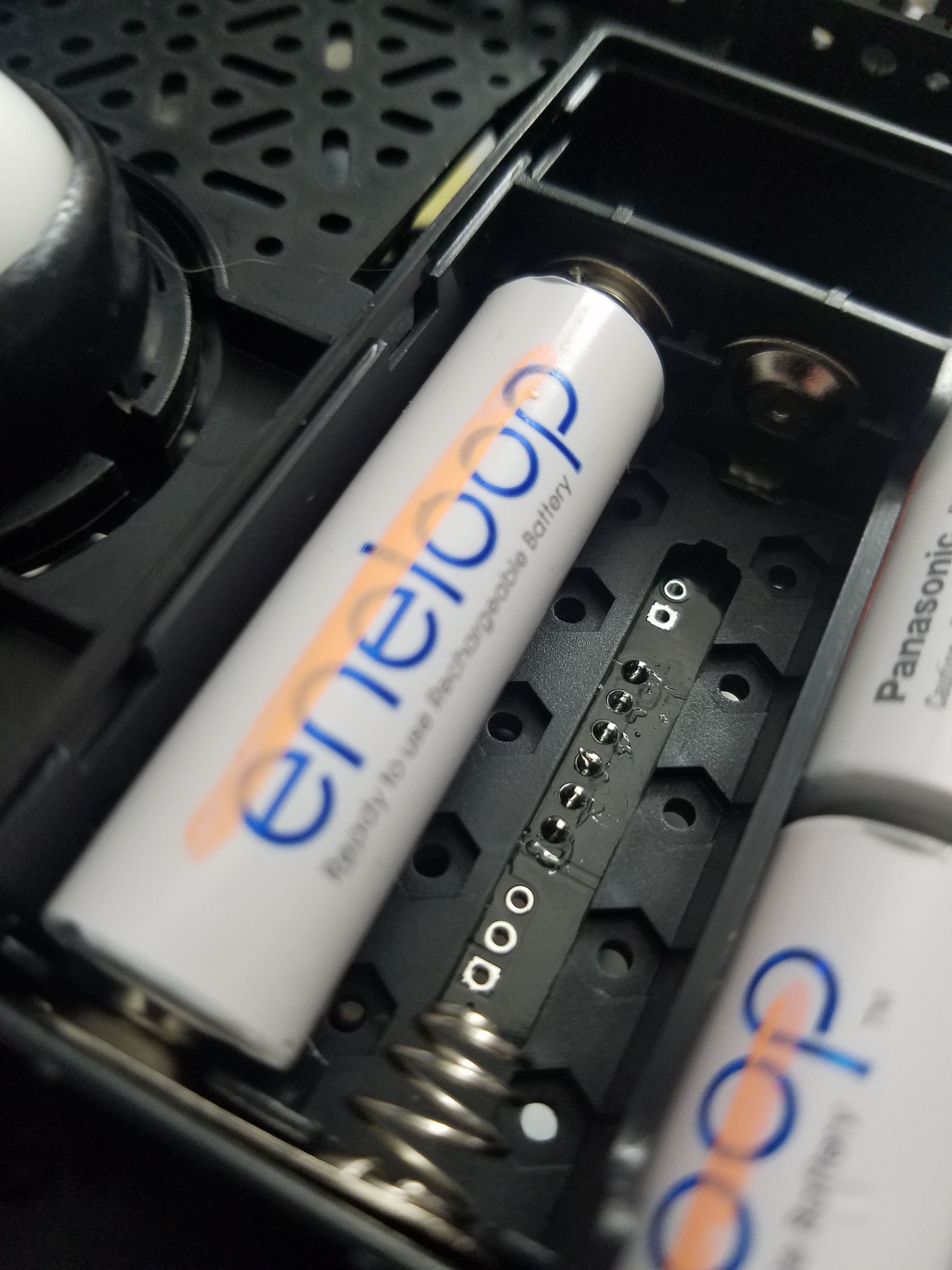
Not a problem - here’s a pic of the soldered headers; they seem OK right? I could try testing the connection from wire to chip but just afraid of damaging something trying to scrape away solder mask/getting access to the DIR/PH pin. Any suggestions?
The soldering on those pins seems fine, so it does seem likely the driver is damaged. I am not sure what might have happened. We test all of our boards, so it was likely working at some point, but something subtle or inadvertent like ESD might have damaged it. If you email us at support@pololu.com with your order information and a reference to this thread, we can help you out with a replacement.
