Hi Pololu Team,
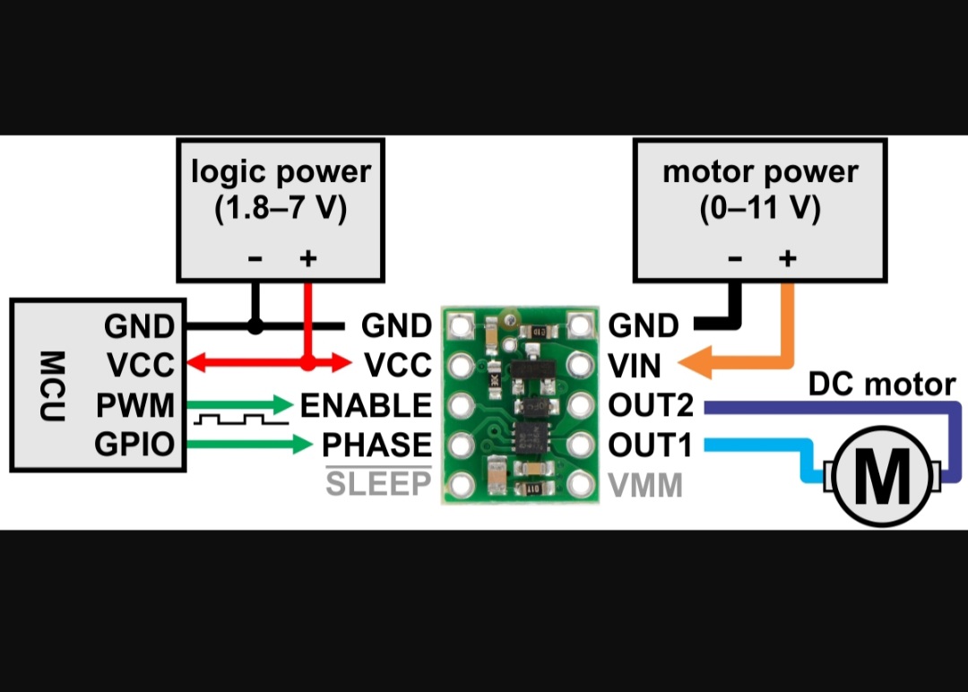
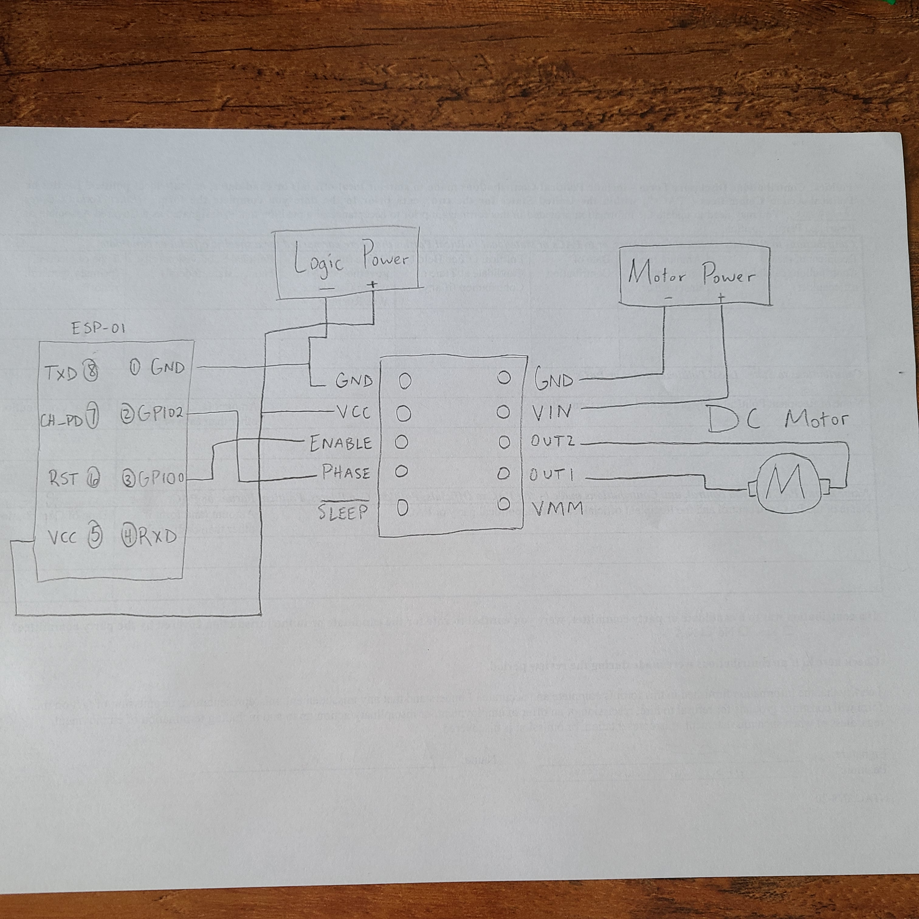
I replied on another person’s forum post (Drv8838 + esp8266 - #4 by arwilliams) however it is a year later reply so I am unsure if the notification is being received by team. Anyhow, I appreciate your responses to everyone’s postings in the forum. My situation is I am using the ESP01 as my MCU and following the DRV8838 diagram to wire my project (pictures included). However, I’m having trouble programming the ESP01 to control the DRV8838 and ultimately the DC motor. Am I missing something or do I need to change my pin connections? Currently in my code, I have enablePin set to 2 and phasePin set to 3. Let me know if you have any questions.
Thanks,
Aaron
Hello, Aaron.
I am sorry I missed your initial post. Specifically what behavior are you seeing when you try to run your system? Can you connect ENABLE and PHASE on the DRV8838 to VCC on your ESP-01 and tell me if the motor runs?
-Jon
1 Like
Hi Jon,
Thanks for the response. I tried to connect the Enable and Phase pins from the DRV8388 to the VCC on the ESP-01 like you suggested and our result was the same, no motor movement. I believe it is due to the code I am currently running. Does the code below look correct to you?
int enablePin = 2;
int phasePin = 3;

void setup()
{
  pinMode(enablePin, OUTPUT);
  pinMode(phasePin, OUTPUT);
}
void loop()
{

  digitalWrite(enablePin, HIGH);
  digitalWrite(phasePin, HIGH);
  delay(100);
  digitalWrite(enablePin, LOW);
  digitalWrite(phasePin, LOW);
  delay(500);
  digitalWrite(enablePin, HIGH);
  digitalWrite(phasePin, LOW);
  delay(100);
  digitalWrite(enablePin, LOW);
  digitalWrite(phasePin, LOW);
  delay(500);
}
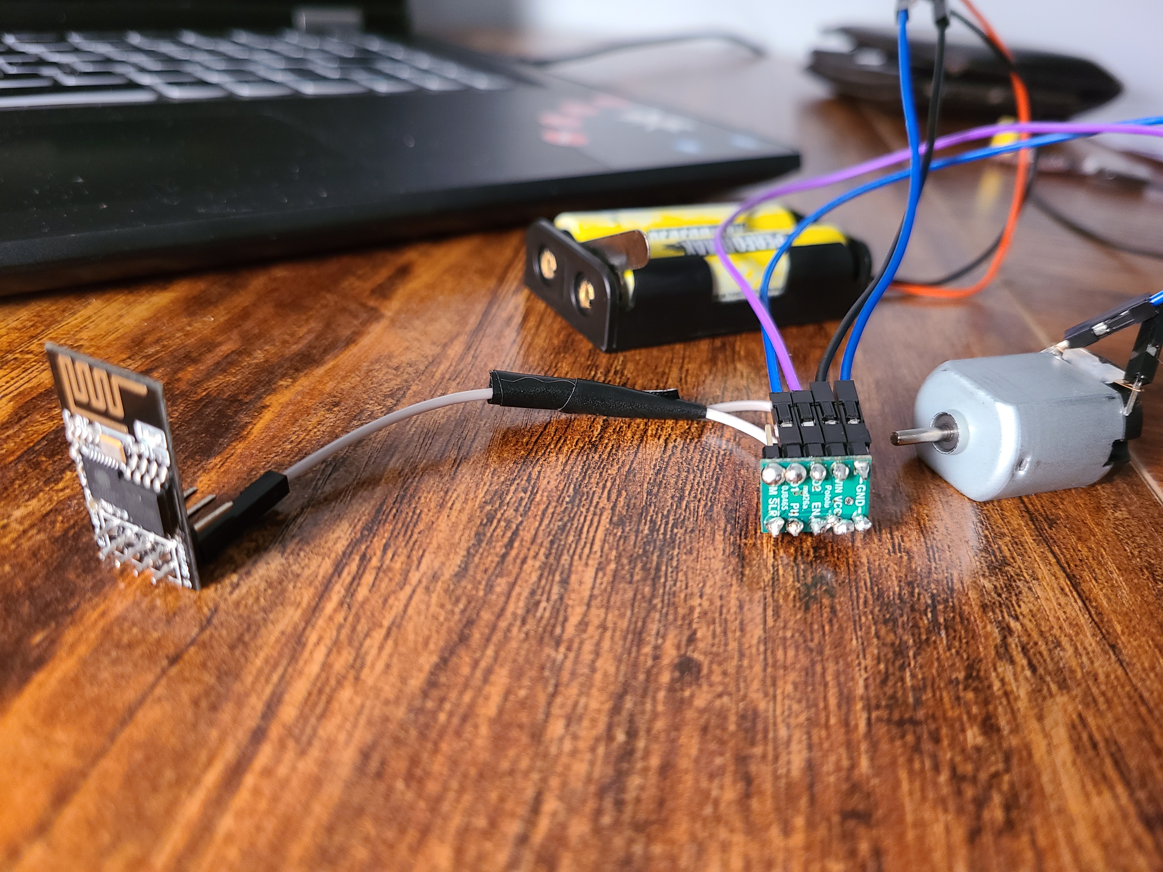
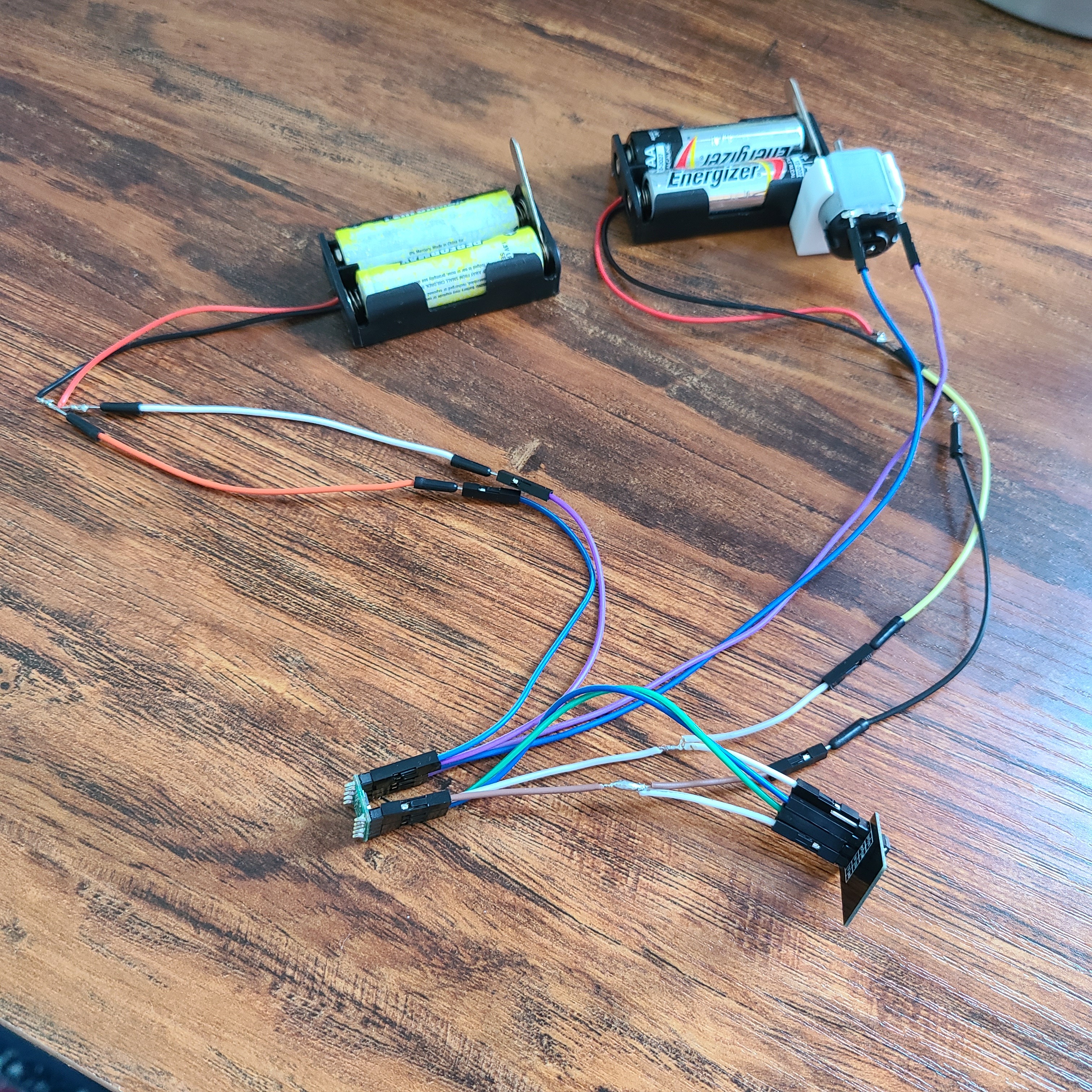
I have included pictures of my current wiring set up. Thanks in advance for your help!
Thank you for including more high-resolution photos. Based on those pictures, it looks like your electrical connections are not good, which is almost certainly the cause of your system not working, especially since the motor does not turn when PHASE and ENABLE are connected to VCC.
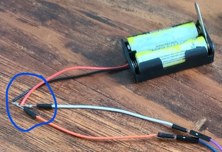
There are several issues with your connections. First, most of the soldered joints on your DRV8838 do not look completely wetted. I recommend reheating those joints to look more like the ideal joints in this Adafruit guide to soldering. Second, the ends of the wires coming from your battery are frayed, which means those wire strands are not well connected to their crimp pins. I recommend replacing those connections. Third, simply inserting the ends of your crimp pins inside the hole of the tabs on your motor is not adequate enough of an electrical connection. Those connections should be soldered.
In general, I think it is also useful if you check your connections with the continuity function of a multimeter before applying power and trying to control your motor. If the multimeter shows that those connections are good, you should focus on testing with PHASE and ENABLE connected to VCC. We can work on your code after your connections are properly set up.
-Jon
Hey Jon,
Thank you for your reply. I re-wetted the joints and strengthened the wire connections as well as soldered the crimp pins to the motor. After doing this all, I have power to the motor and ESP01. When I turn on the power, the motor runs but does not stop. I am trying to use a program on my phone and the ESP via wifi to control the motor on and off. Does my code look appropriate to control the DRV?
Thanks for your help!
Aaron
int enablePin = 2;
int phasePin = 3;
// deviceId is the ID assigned to smart-home-device
void turnOn(String deviceId) {
  if (deviceId == "5ebc95b8d13d5c20309317d7") // Device ID
  {
    Serial.print("Turn on device id: ");
    Serial.println(deviceId);
  digitalWrite(enablePin, HIGH);
  digitalWrite(phasePin, LOW);
  }
}
void turnOff(String deviceId) {
   if (deviceId == "5ebc95b8d13d5c20309317d7") // Device ID
   {
     Serial.print("Turn off Device ID: ");
     Serial.println(deviceId);
  digitalWrite(enablePin, LOW);
  digitalWrite(phasePin, LOW);
   }
}
void setup()
{
// setup wifi
WiFi.begin(MySSID, MyWifiPassword);
// while having a wifi connection continue to output to the enable and phase pins
//while (WiFi.status() == WL_CONNECTED) {
pinMode(enablePin, OUTPUT);
pinMode(phasePin, OUTPUT);
//}
}
I just noticed in your most recent pictures that you only had a single wire going from your ESP01 to the DRV8838. If you were trying to test the driver by connecting ENABLE and PHASE to VCC like I mentioned before, you still would have needed to have the DRV8838’s GND and VCC pins connected as well so that it had a common ground and a logic voltage. If you got the motor running, it sounds like you might have figured that out and made the proper connections already. Have you since connected the ENABLE and PHASE pins back to pins 2 and 3 on your ESP01 as your program expects? Could you post an updated picture of your connections? A wiring diagram or a list of your connections would also be helpful since it can be difficult to see which pin each wire connects to in the pictures.
I don’t see any obvious problems with your code, but it looks like you might not have posted your entire program. I do not see any calls to your turnOff() and turnOn() functions; are they in the loop() function, which you did not post?
-Jon
Hi Jon,
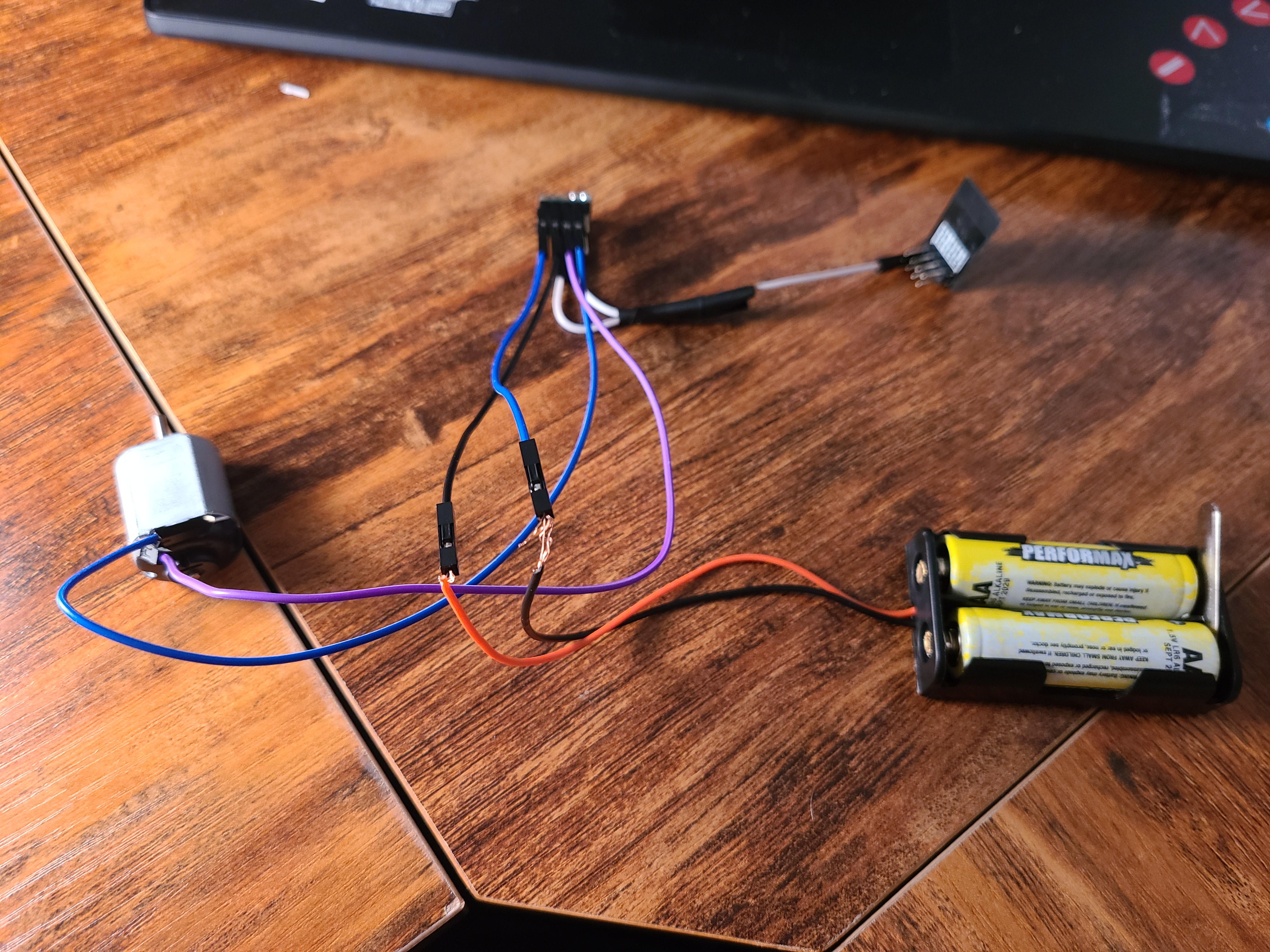
Correct - I added a common ground and logic voltage. I also connected PHASE and ENABLE to pins 2 and 3 on my ESP01, respectively. Attached is an updated picture of my connections as well as a wiring diagram.
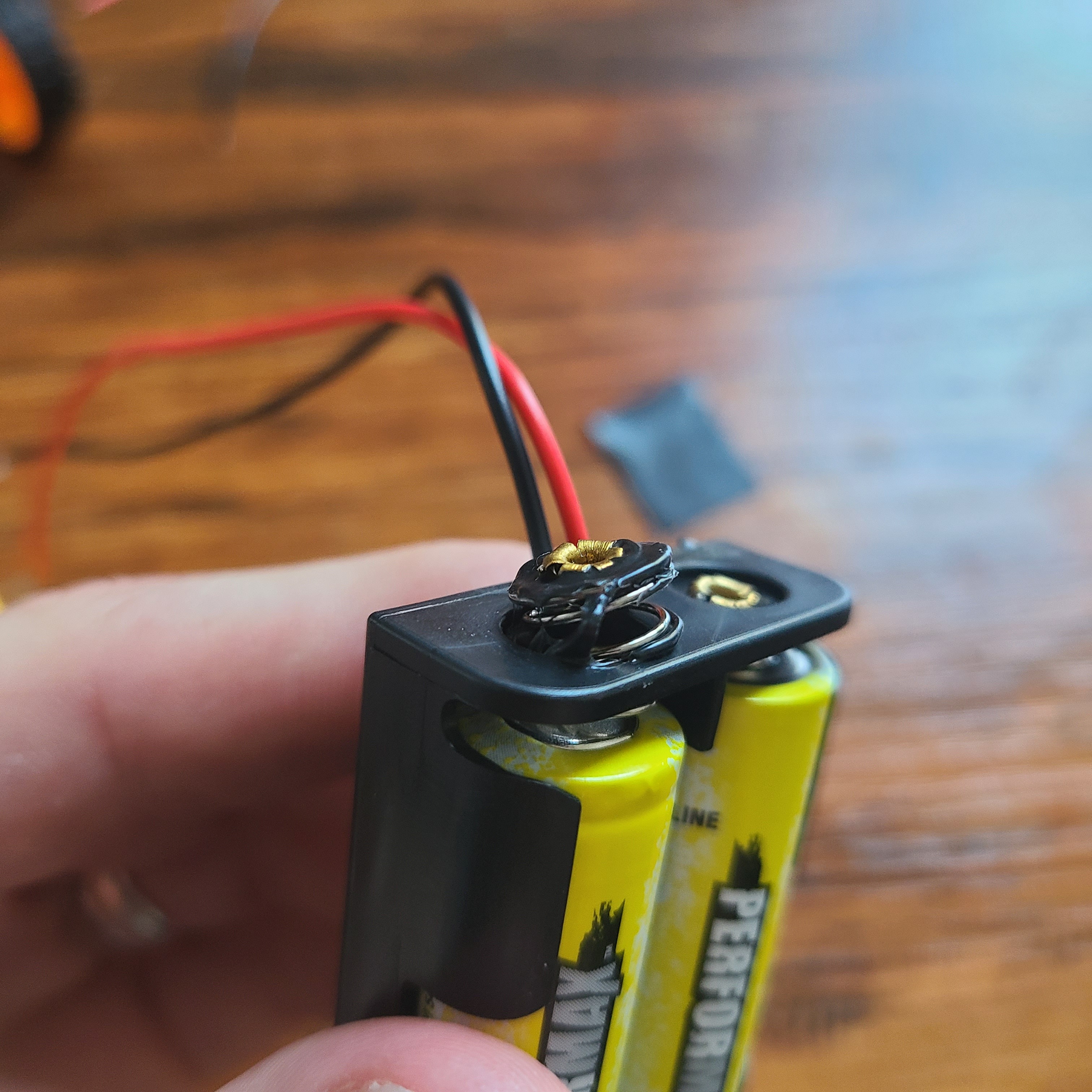
Ignoring my previous code, I have been experimenting more with the DRV as well as simpler code to control a DC motor. Below is my most recent test. When I power the project, the motor runs, stops, runs, and stops again on 3 second intervals. However, while the program is running, I can hear a loud beep noise coming from the motor as if the motor is stalling out. Is there something in my code that is causing damage or is there a better way to code the on/off functionality of the DC motor via the DRV? As a side note, when I ran the code one of my AA batteries (powering the MCU) overheated and melted the battery holder.
Thanks for your help!
Aaron
const int ENABLE = 3 ; //initializing pin 2 as ENABLE
const int PHASE = 2 ;
const int SLEEP = 4 ;
//providing logic to choose the direction of the DC motor

void setup() {
   pinMode(ENABLE,OUTPUT) ;
   pinMode(PHASE,OUTPUT) ;
   pinMode(SLEEP,OUTPUT) ;
}

void loop() {
   // Clock wise motion
   digitalWrite(PHASE,HIGH) ;
   digitalWrite(SLEEP,LOW) ;
   analogWrite(ENABLE,255) ;
   delay(3000) ;
    //brake for 3 secs
   digitalWrite(PHASE,HIGH) ;
   digitalWrite(SLEEP,HIGH) ;
   delay(3000) ;
   // Counter Clock-wise motion
   digitalWrite(PHASE,LOW) ;
   digitalWrite(SLEEP,HIGH) ;
   delay(3000) ;
   //brake
   digitalWrite(PHASE,HIGH) ;
   digitalWrite(SLEEP,HIGH) ;
   delay(3000) ;
}
I suspect the audible beep you hear is because you are using the analogWrite() function to generate a PWM signal, and that function switches the microcontroller pin at an audible frequency (which looks like 1 kHz by default). This can be heard as noise coming from the motor.
I am not entirely sure why the plastic melted on your battery holder. In general, things melting is from a large amount of heat being generated, but I would not expect your circuit to normally draw enough current to melt anything. It might be that there is a short somewhere in your system, or that that particular battery was bad (especially if only one of them heated up while the plastic was melting), or maybe a bad connection with high resistance.
By the way, the SLEEP pin on the DRV8838 is inverted (logic high results in normal operation), and once you start the PWM on the ENABLE pin, you never change or stop it. So, the behavior of your Arduino sketch is actually doing the following: disable the outputs, wait 3 seconds, rotate one direction, wait 3 seconds, rotate in the other direction, wait 3 seconds, rotate in direction one, wait 3 seconds, and repeat.
-Jon
I just noticed that in the picture of your connections the exposed metal of the pre-crimped connectors on the wires coming out of your battery are very close to each other. A short here between battery power and ground would definitely draw lots of current, and could be the source of your melted battery holder.