
I’ve recently bought some DRV8835 motor shields, product at https://www.pololu.com/product/2511
When using phase/enable mode, the output voltage looks clean; the output voltage waveforms are crisp both on the way up and on the way down. After severing the mode trace in order to put the driver in IN/IN mode, however, I end up with voltage ramping down very slowly after each step, even with nothing hooked up to the driver, but ramping up instantly. This also happens if I put a small load resistor between the terminals. My logic voltage is 5V and my motor Vin is 2.3 V off a benchtop power supply. The arduino is being powered off of USB and there is no pin connecting board AVIN to to Arduino VIN. This issue appears both on motor 1 and motor 2. I am driving one pin with ~500 Hz PWM and the other is staying low. I have not yet been able to determine whether the same issue appears if I drive M1A instead of M1B. The DRV 8835 datasheet specifies an output fall time around 160 ns in IN/IN mode. I have seen this behavior with 2 drivers. I ordered 5, but I’m hesitant to use more in case I’m doing something wrong.
I have used a scope to probe the DRV8835 outputs and discovered that this issue appears to be coming from the IC directly. There is no ramping in the PWM signal hitting the chip inputs, but the same ramping is present on the chip outputs.
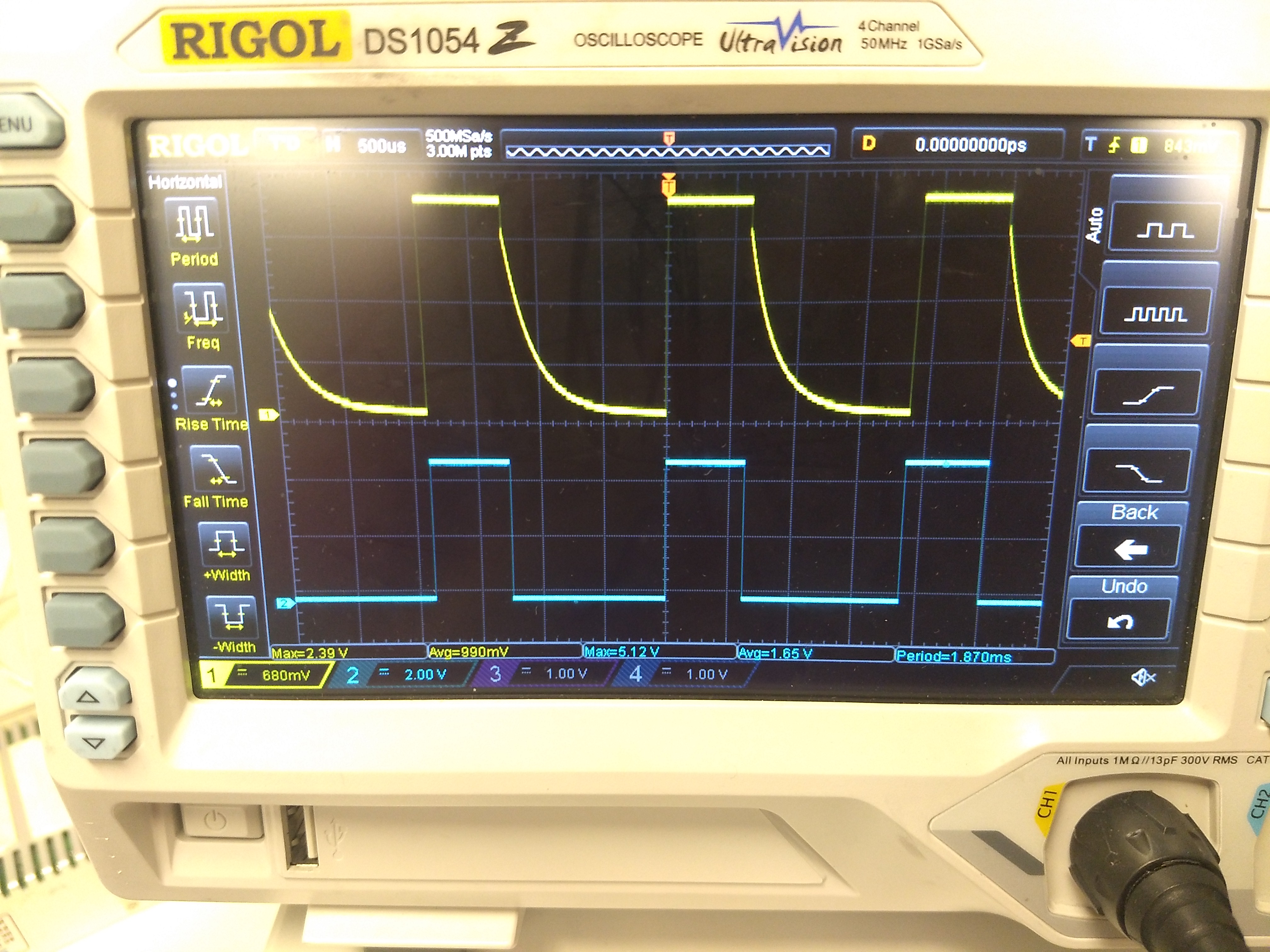
I have attached a photo of the output voltage with no load between the motor 1 terminals. Channel 1 (yellow) is the voltage between the motor 1B terminal and arduino ground and channel 2 (blue) is the voltage between arduino pin 9 and arduino ground.
Any idea why this might be happening, and whether it could be a problem with the DRV8835 chip itself?