DRV8835 for model railroad

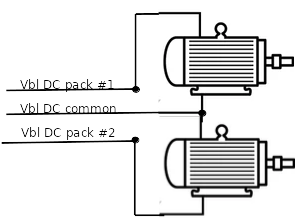
I have a model railroad which uses two power packs to provide DC voltage to two different sets of tracks. The tracks utilize a common rail system- - that is, the two packs provide up to +12 volts DC and use a common ground. Because there are two independent power packs using 117 volt AC current to provide the power, the two independent DC motors in the locomotives running on this system can be controlled separately.

image

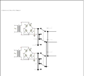
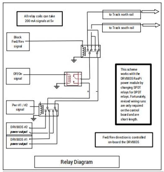
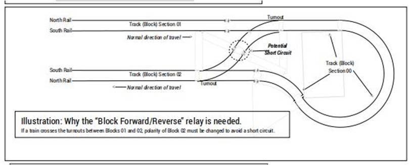
SPDT relays to select which power pack supplies which individual track section, and DPDT reversing switches for each track section, are not shown here. The above circuit works because the two transformers are isolated from each other. (Trying to use a single power pack to power both sides of the circuit results in a short circuit.)

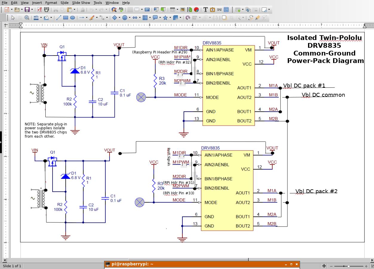
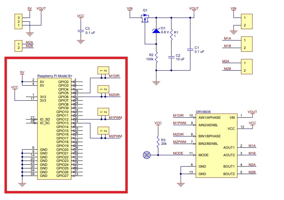
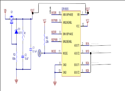
I am in the process of adding a Pololu DRV 8835 Dual Motor Driver Kit and a 9 volt DC plug-in power source to my Raspberry Pi. The computer already controls everything on my layout except the power packs. I’m concerned, though, that the common rail system may not work because the two current sources on the DRV8835 board, which go to the tracks, may not be independent. The proposed setup is as follows:

image

Could one or two of you electronics gurus out there give me some advice? This is “above my pay grade.”

Pondering my own post overnight, I thought I might try adding a second Pololu board, soldering in a 40-pin header in place of the one that comes with the kit so I could stack two of 'em, and somehow use different GPIO pins to control the thing. That way, I could isolate the two power supplies from each other by using separate plug-in power supplies, like I’m currently doing with model railroad power packs.

The article, “Pololu DRV8835 Dual Motor Driver Kit for Raspberry Pi B+” states, in part, “The board uses GPIO pins 5, 6, 12, and 13 to control the motor driver, making use of the Raspberry Pi’s hardware PWM outputs, although the pin mappings can be customized if the defaults are not convenient.” I’ve been searching for a post which would cover how to do this, but haven’t found one yet. It probably involves cutting some traces and wiring a few jumpers. (Yikes! That’s scary!) …any guidance?

Hello.

The pictures you are posting of your schematics are low resolution, but I can see the proposed setup from your first post shows M1B and M2B being connected, which you definitely should not do, especially if you want bi-directional control.

It seems like it should be fine if you just use a single DRV8835 Dual Motor Driver Kit for Raspberry Pi with one set of tracks connected to the M1 outputs and the other set of tracks connected to the M2 outputs. When you use the driver, each set of outputs can be controlled completely independently of the other, but they will always apply the supply voltage with respect to the same GND.

- Patrick

Thanks, Patrick. I was afraid of that, which was why I posted the question. This forum works! It saved me the grief of “smoking” your card.

Sorry about the low resolution. I’ll try to do better on my next post, which will have a diagram for my second post above, namely using two separate Pololu DRV8835 cards with the 11 volt inputs isolated, sourced by separate plug-in power supplies. This way I can also use each card’s outputs in parallel to provide a higher output current (if needed). That’s comforting.

Unfortunately, I can’t connect the various track segments the way you suggested. Using the common ground system that I did cuts the number of necessary wires nearly in half, which is significant when using 50-pair cables to connect the layout to the control panel! Assuming I didn’t use the common ground scheme and supplied each track segment separately, I would also have to rip out a significant number of SPDT relays and replace them with DPDT relays. This certainly could be done, but would require completely revising the arrangement of the control system’s main board. That means re-wiring most of the main board. Ouch!

So, I’ll draw up a proposed schematic and hope for some constructive criticism and sanity checking. Your customer who needs to drive four motors independently will probably be interested in this schematic too. Ah, life on the “bleeding edge,” huh?

>>>>>WARNING! SEE POSTS BELOW FOR POLOLU CORRECTIONS!<<<<<
UhOh! …one more problem: GPIO pin conflicts.

I looked up the Raspberry Pi GPIO pinout for the DRV8835 Pololu board as well as two boards that I use to interface my relays, which are AB-Electronics “IO Pi Plus” boards utilizing I2C. Aarrggh! The pin assignments overlap!

Conflicts with I2C boards are as follows:
IO PI PLUS CARD… … … … … … DRV8835 CARD
GPIO 0 (I2C0_SDA pin 3… … … …- - -
GPIO 1 (I2C0_SCL) pin 5… … … …M1B
GPIO 4 (GPCLK0) pin 7… … … … .M2A
GPIO 14 (UART0_TXD) pin 8… …- - -
GPIO 15 (UART0_RXD) pin 10… …M1DIR
GPIO 10 (SPI0_MOSI) pin 19… … - - -
GPIO 9 (SPI0_MISO) pin 21… … …M1PWM
GPIO 11 (SPI0_SCLK) pin 23… … - - -
GPIO 08 (SPI0_CE0_N) pin 24… …M2DIR
GPIO 07 (SPI0_CE1_N) pin 26… …M2PWM

Looks like I’ll have to reassign the conflicting pins on the Pololu board, plus reassign a different way on the second Pololu board if the solution I described above works out. Yikes!

…any comments? (other than, maybe, as Ren & Stimpy used to say, “You EEEDIOT!” if I try this :frowning: .)
>>>>>WARNING! SEE POSTS BELOW FOR POLOLU CORRECTIONS!<<<<<

There should not be any conflicts between your IO Pi Plus and our DRV8835 kit for Raspberry Pi. I think you are confusing the Raspberry Pi GPIO pin numbers with the physical pin numbers. Our DRV8835 kit for Raspberry Pi uses GPIO pins 5, 6, 12, and 13 (physical pins 29, 31, 32, and 33 respectively). The I2C pins on the Raspsberry Pi are GPIO pins 2 and 3 (physical pins 3 and 5).

Of course, if you use two drivers you will still need to remap some connections. However, I do not understand how you determined using two separate motor drivers reduces how much wiring you need to do. I strongly recommend posting a diagram of your proposed connections so I can check them out. (If it’s easier, you could even leave out the logic connections for now so we can just focus on how you are using the driver outputs.)

Also, you have M1B and M2A in your list of conflicts, but those are the motor driver outputs. They do not connect to anything on the Raspberry Pi. I suggest reviewing our product page documentation again to ensure that you understand how it works.

- Patrick

Thanks again, Patrick. Here’s a hopefully corrected list of the RasPi header pin-outs. As you say (thank goodness) there are no conflicts. Please check me- - these things do not match what signals are shown on the DRV8835 schematic! I’ve made some assumptions on what signals your board’s pin-outs match.

Corrected:
RasPi header pin-outs are as follows (pin # is RasPi header physical pin #):
IO PI PLUS CARD … … … … … … DRV8835 CARD
GPIO 0 (I2C0_SDA pin 3… … … …- - - (not connected)
GPIO 1 (I2C0_SCL) pin 5… … … …M1B (not connected)
GPIO 4 (GPCLK0) pin 7… … … … .M2A (not connected)
GPIO 5 (not connected)… … … … …M1DIR pin 29 <–please check signal name
GPIO 6 (not connected)… … … … …M2DIR pin 31 <–please check signal name
GPIO 12 (not connected) … … … …M1PWM pin 32 <–please check signal name
GPIO 13 (not connected)… … … …M2PWM pin 33 <–please check signal name
GPIO 14 (UART0_TXD) pin 8… …- - - (not connected)
GPIO 15 (UART0_RXD) pin 10… …M1DIR (not connected)
GPIO 10 (SPI0_MOSI) pin 19… … - - - (not connected)
GPIO 9 (SPI0_MISO) pin 21… … …M1PWM (not connected)
GPIO 11 (SPI0_SCLK) pin 23… … - - - (not connected)
GPIO 08 (SPI0_CE0_N) pin 24… …M2DIR (not connected)
GPIO 07 (SPI0_CE1_N) pin 26… …M2PWM (not connected)

quoted from Patrick’s post above: DRV8835 kit for Raspberry Pi uses GPIO pins 5, 6, 12, and 13 (physical pins 29, 31, 32, and 33 respectively). The I2C pins on the Raspsberry Pi are GPIO pins 2 and 3 (physical pins 3 and 5).

Here’s my latest try at isolating two DRV8835 boards and using a common return. Using two separate plug-in power supplies, one for each board, should hopefully isolate them. (At any rate, this trick works using two conventional model railroad power packs. That’s what I’m using now. It may not work if the chip’s internal circuitry connections are different from what I think they are.) The diagram can be seen at a better resolution if you click on it. Note where various input leads are “severed” on the diagram.

How about looking over the circuit and giving suggestions, please. Note that I have updated the RasPi header pin numbers per Patrick’s guidance (hopefully correctly). The schematic pin numbers on the smaller (carrier) board don’t necessarily correlate with the Pololu implementation- - thanks to Patrick for getting that part straightened out for me. … …but you’d best check that part, too.

Thanks for your help.

My initial impression was that your goal is to control two DC motors (for your locomotives) independently, and presumably you would need bidirectional control to make them go forwards and backwards (i.e. you are planning to connect the motor outputs straight to the tracks and not powering anything else with them). If that is the case, then you should not be tying any of motor driver output channels together, regardless of how the drivers are being powered, so this setup has the same problem as the first setup you proposed.

However, it is starting to seem like I am misunderstood how you are planning to use the DRV8835 in your setup. Can you clarify exactly what exactly you are planning to connect to the motor driver outputs? What are the Vbl DC pack #1 and Vbl DC pack #2 labels representing in your schematic?

By the way, the pin numbers you are referring to on our schematic are the DRV8835 chip’s pin numbers, not the Raspberry Pi pin numbers, which is why they do not match up. The Raspberry Pi pin numbers that our board connects to are visible on the element of the schematic representing the Raspberry Pi. I posted a picture of the schematic below with the Raspberry Pi element boxed in red.

- Patrick

Thanks for a great response. I thought I would post this in the morning, but as it turned out, replying by email, it popped up right away.

The reason for the two outputs is that it must be possible to run two different trains on separate track segments at the same time; for example, running a passenger train down the main line while, separately, a switch engine sorts freight cars on a separate siding area traditionally called a classification yard.

The two trains have nothing in common electrically or mechanically, other than keeping out of each other’s way by staying off the other train’s track section. They always operate on separate sections of track. To make sure of this, the outputs from pack #1 and pack #2 can never be connected to the same track section. Relays (not shown in my diagram) ensure this. I would have included the full diagram, but it gets real busy, real fast! (…talk about low resolution, to fit it all on a one-page diagram!)

Thanks for the Raspberry Pi schematic with pin-outs listed. I’m sure that anyone else who dares peek at this series of posts will need all the clarification they/we can get. …big help!

So, the rambling explanation above is as clear as mud, huh? Sorry about that. I hope this clears up any misunderstanding about what I’m trying to accomplish, at least a bit. Thanks.

Russ

We are not experts about model railroads so it is still not clear to me what you are planning to connect to the motor driver outputs and specifically what you want each driver output to do. Without a more concrete understanding of that, I do not have much more advice to offer beyond what I have already pointed out, which is that tying the motor driver outputs together as shown in your diagrams does not seem useful and is likely to risk damaging the drivers.

It also seems like you still do not have a good understanding of how our drivers work. While we can answer specific questions about their operation and offer help with their intended use (bidirectional driving of DC motors), your proposed application seems specialized enough that I suspect you might get better advice by seeking out a model railroad builder who is also familiar with electronics like these motor drivers. Unfortunately, I do not have any specific recommendations for where you could find someone like that, but maybe you could try looking for other examples of motor drivers being used in a similar way at a model railroad forum.

- Patrick

Sorry for the obfuscation on the model railroad. To be honest, you don’t really need to understand all the model railroad jargon. All we need to do is control two DC motors, bi-directionally as you noted, but do it with two wires feeding them and a single common wire completing the circuits. (See below.) This connects to the preceding diagram of August 5th, with the two motors positioned to the right and the connections made as labelled.

Hopefully this explains things better. There is considerable incentive for me to be able to utilize this scheme, seeing as how it cuts the amount of 50-wire cable I must use in half! The advantage is gained by using two separate 110 volt transformers.

Yeah, this approach seems a bit mystic, but then, most electronic circuitry is that way. I confess that I took my one-and-only electrical engineering course back in 1966, before transistors and IC’s replaced vacuum tubes, and the course emphasized power distribution. Thanks very much for Pololu’s work, and for your help and patience.

Russ
image

You cannot independently control two motors with a scheme like that and preserve their ability to turn both directions (at least not without much more complicated control electronics). For bidirectional control, current needs to be able to flow both directions through the motor, which is not practical in a setup like you proposed since, for example, Vbl DC common might need to simultaneously act as a current source for motor one and a current sink (ground) for motor two.

Maybe you could make a system like this work if you had something that can apply negative voltages, but our drivers (and most H-bridge motor drivers in general) do not do that. Instead, they hold one output high and the other at ground to drive the motor in one direction and swap the outputs to drive in the other direction.

- Patrick

Thanks, Patrick. Your comment,

“…our drivers (and most H-bridge motor drivers in general) do not do that. Instead, they hold one output high and the other at ground…”

says it all. There is a board-level ground connection, which rules out my “floating ground” approach. Board circuitry and power circuitry can’t be separated.

Soooo… looks like I need to do a re-design of the [not shown above] relay logic (rip out one, maybe two, SPDT relay boards in favor of DPDT boards), add wiring, possibly add another 50-pair cable between control panel and layout… (sigh). Maybe I can avoid that second DRV8835 board when I can verify that the current draw of the two DC motors is within board limits. I’ll check that when I get back home to the layout.

I very much appreciate your help, especially your clarification of the RasPi header pin-outs. Sorry for all the confusion and jargon. I’ll post again, as soon as I can get back to the layout hardware. (…two months or so.)

Russ

If you find out your current draw is too high for one motor driver to handle, a better alternative than getting two DRV8835 dual driver kits would probably be to just get an altogether more powerful driver. We have several motor driver expansion boards for Raspberry Pi, including our Dual G2 High-Power Motor Drivers for Raspberry Pi which can handle several amps, though you might also be okay with a lower power option like our dual TB9051FTG or the dual MAX14870.

- Patrick

Thanks, Patrick. Digging around on the internet, folks suggest that an N-Gauge locomotive (single DC motor) draws about 0.25 amps, and an HO-Gauge motor draws about 0.5 amps, so I think I’ll be okay with your DRB8835 board as long as I don’t try to run more than a couple of locomotives (called “double-heading”) at a time.

I’ve re-thought the wiring in light of the above, and have a workable solution which shouldn’t cause much re-wiring pain. As it turns out, I can substitute a DPDT relay board for one of the existing SPDT boards, which I call the “Power #1/#2 relay,” and run relatively short wires to accomplish what is needed. The DPDT relay swaps BOTH wires, not just the one which I was doing in my previous SPDT scheme. (Mounting the new board and revising the RasPi’s I2C cabling may be the major challenge, but fortunately it’s doable without TOO much trouble.)

Here’s a shot of the new circuit diagram.

You’re probably wondering why there’s what looks like an extra "Block Fwd/Rev relay, right? After all, there’s forward/reverse control built into the DRV8835 chip. Well, here’s an admittedly crude explanation of the reason:


As it turns out, trying to cross over from a track going one direction to another track going the other direction can cause a problem, because the polarity of the two tracks are different. The solution is to change the second track’s polarity to match the first track. The track connections in the diagram’s “short circuit” detail are called “insulated rail joiners.”

Another “clear-as-mud” explanation, probably, but for those who care about things, here’s the solution. This will allow computer control of the whole layout, now thankfully including motor speed control. Each track section, or “block,” needs the hardware shown in the “Relay Diagram” sketch above, but by using 8-relay boards, it’s not too awfully time consuming or expensive. (This is supposed to be fun, right?) Thanks for developing the great board that will make it possible.
Russ

BTW what power supply is recommended for supplying the 11 volts DC to the Pololu DRV8835 board? What’s user experience, powering this little jewel?

I do not see any obvious shorting hazards with your new proposed connections, or anything else that would obviously be bad for the driver, though I am not sure whether some of the elements your are connecting are redundant.

I would not recommend connecting the DRV8835 to an 11V supply. The maximum operating voltage listed under the “Specs” tab is 11V, so an 11V supply leaves you no safety margin. If it is important for you to use a voltage around that level, I would suggest using our Dual MAX14870 Motor Driver for Raspberry Pi instead.

As far as specific power supplies, you can check out our selection of wall power adapters, but we do not have any that supply 11V.

- Patrick

Thanks for the good advice. I just ordered a Dual MAX14870 from your website, and will power it with a wall power adapter. I thought about using an existing model railroad power pack, but some idiot (me) would probably try to use the reversing switch on it and wipe out your board or worse. To make it more idiot proof, I next considered putting together a bridge rectifier so polarity would always be correct. However, with the ready availability of power supplies these days, powering with a dedicated wall power pack is simpler, cheaper, and safer. I’ll use a 40-extended-pin header in place of the one supplied with the kit, so I have the option of continuing to build skyward on my Raspberry Pi.

Looks like your recommended board does everything I need. The 1.7 amps per channel is plenty for my needs, the option to feed 12 volts DC is ideal (compatible with other existing 12 vdc needs), and the price is great. great work, guys!

Russ

I am glad to hear you are impressed with the board! Just in case you missed it, our Dual MAX14870 Motor Driver for Raspberry Pi includes a reverse voltage protection feature that helps keep the driver from operating or being damaged if power is connected to VIN and GND backwards (though it is still best to avoid needing that protection if you can help it).

- Patrick