I am using the Pololu DRV8834 Low-Voltage Stepper Motor Driver to drive a JDSU VCF050 tunable optical filter stepper motor.
Motor specifications:
Supply voltage: 3.0–3.3 V
Coil resistance: 17–21 Ω per phase
Rated current: 170 mA per phase
Full-step operation
According to the DRV8834 datasheet and the Pololu documentation, with the onboard 0.10 Ω sense resistors, the current limit is: Current limit = 2 × VREF
To achieve approximately 170 mA per phase, I expect to set VREF around 0.085–0.12 V (depending on the stepping mode).
My issue:
When I measure the VREF test point with a multimeter:
Minimum VREF: ~0.64 V
Maximum VREF: ~1.6 V
The potentiometer rotates correctly, but the voltage never goes below approximately 0-55 - 0.64 V
My setup
VMOT = 3.3 V
Logic voltage = 3.3 V
SLEEP = HIGH
ENABLE = HIGH (during VREF measurement, no motor connected)
Measuring between the VREF test point and GND
The VREF solder jumper is already soldered.
My questions:
Is a minimum VREF of 0.55 - 0.64 V normal on the Pololu DRV8834 carrier?
Should the VREF adjustment normally be able to go close to 0 V?
I expect you should be able to adjust the potentiometer until VREF reads 0V on the DRV8834, but it difficult to set specific current limits that low. Testing out a unit here I could generally adjust the potentiometer to adjust the current limit in steps of approximately 20 mA (10 mV), but that was with good tools (I used a 0.4×2.0mm flat head screwdriver), a pretty steady hand, and probing in a way that let me monitor VREF as I was adjusting the pot (as opposed to going back-and-forth between adjusting the pot, then checking VREF). You can see an example of such a setup in the setting the current limit video shared in this blog post. If you have a setup resembling that and continue having trouble, can you post some pictures of the system showing all your connections (including ones that show how you are probing) as well as close ups of the board?
By the way, since you are powering your driver with a 3.3V supply, you might not need to worry about setting the current limit that accurately anyway. Supposing you set the driver’s current limit well above the motor’s rated current, if the motor coil resistance is around 19 Ω and your supply is 3.3V, then according to Ohm’s law the current draw will be around 174 mA, and while I am not familiar with your particular motor, a few mA one way or the other is probably not going to make a problematic difference. However, setting the current limit is still going to be important if you want to use microstepping.
I will be using microstepping in the final application, so I would like to get the current limit working correctly.
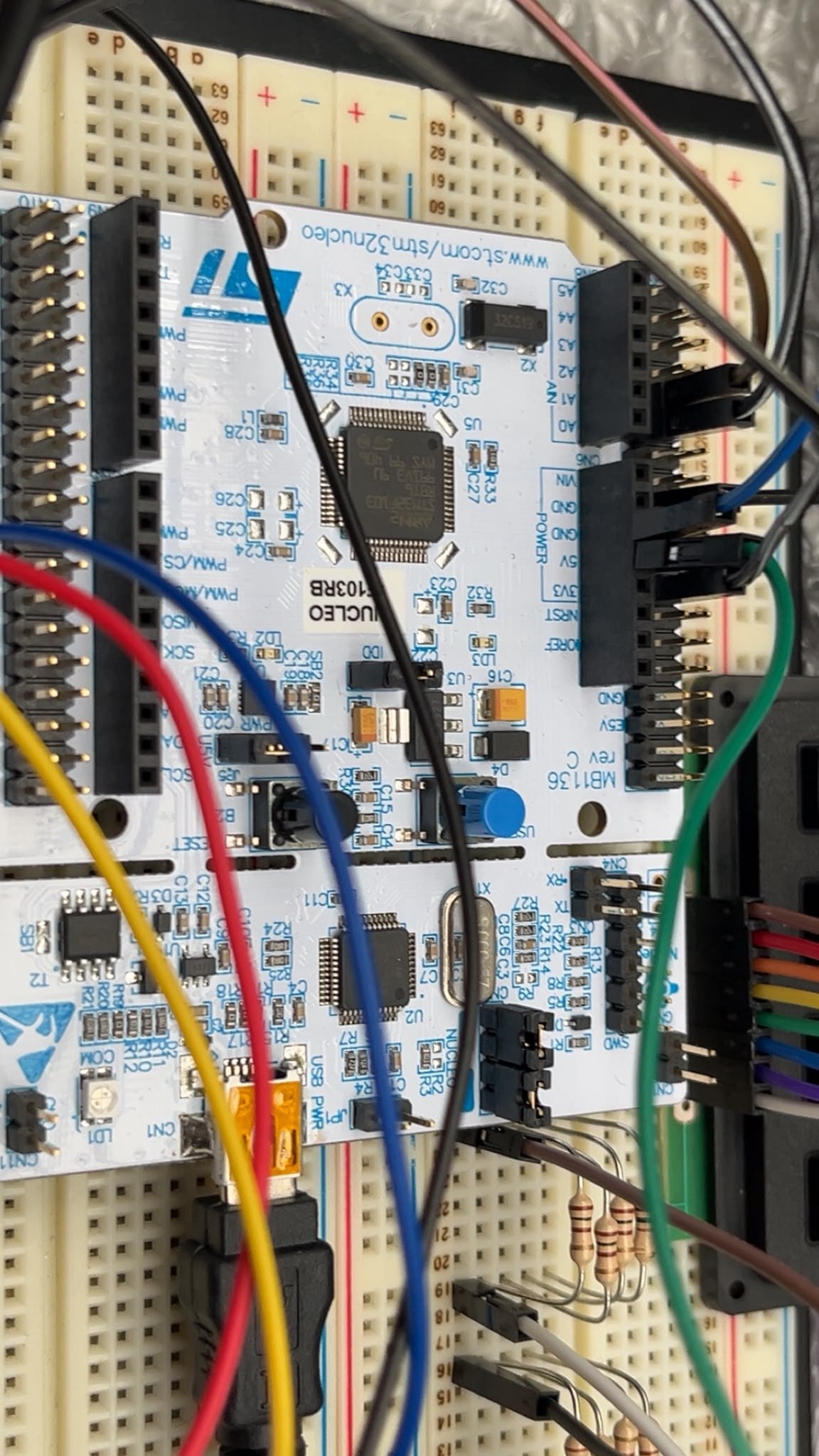
For my current test setup, I have connected the driver as follows:
M0 = GND
M1 = GND (Full-step mode)
STEP connected to PA0 of my STM32 Nucleo board (timer pulse output)
*DIR connected to PA1 of my STM32 Nucleo board
5 V input to a 3.3 V regulator
The 3.3 V regulator output is connected to VMOT of the DRV8834
Common GND is shared between the STM32, regulator, and DRV8834
At the moment, I am only testing the driver and measuring VREF. The motor is not connected while I adjust the potentiometer.
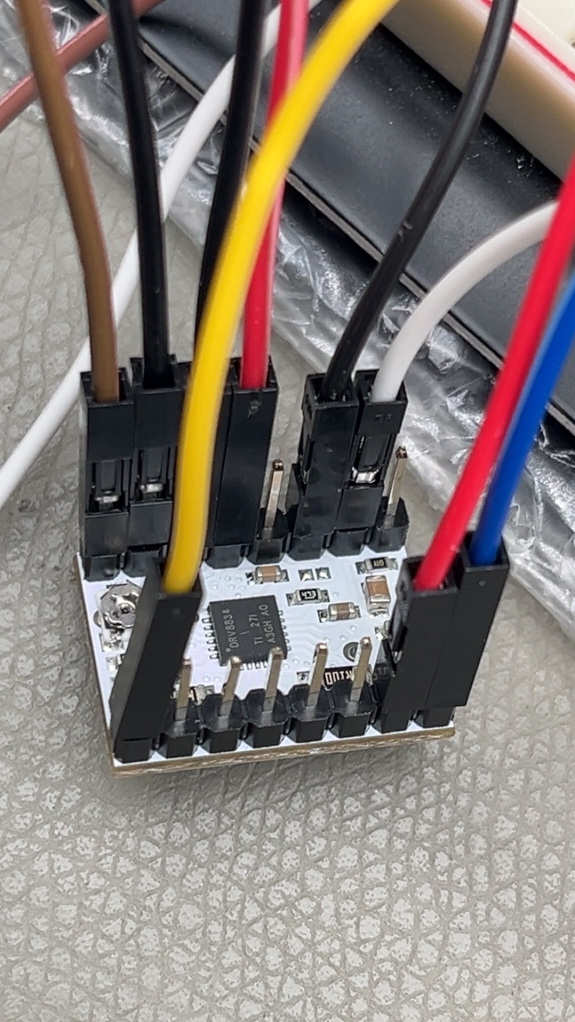
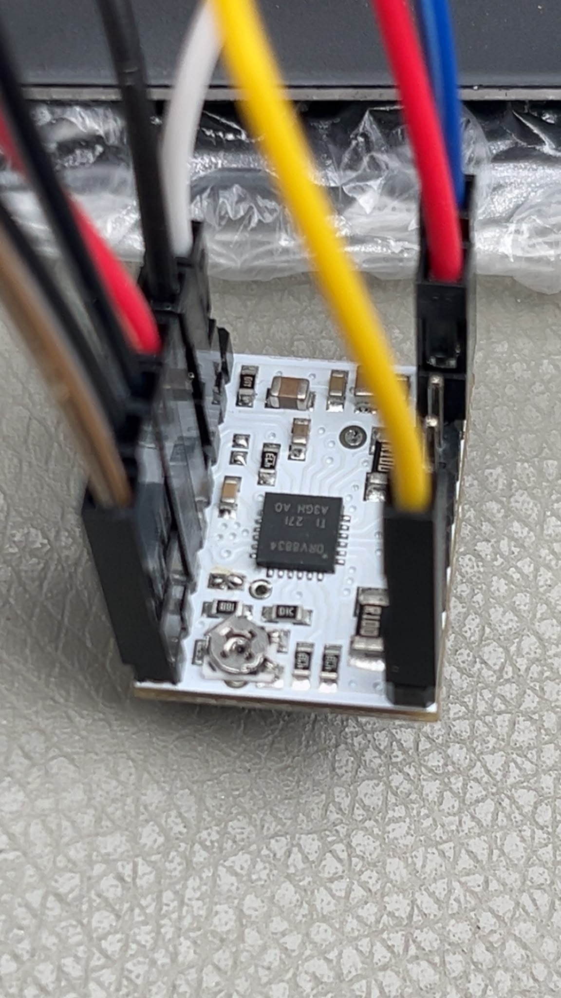
I have attached pictures of my complete setup, close-up images of the DRV8834 board, and a short video showing the VREF adjustment. In the video, you can see that the lowest VREF I can obtain is approximately 0.53 V. I would appreciate it if you could let me know whether the board appears to be functioning normally or if there is anything in my setup that I should change.
Thank you for the pictures and video. It is hard to tell for sure, but it seems like the connection bridging the VREF jumper might not be great; like the solder joints on the two pads are touching each other but not actually melted together. Can you try fixing that and see if that changes the result?
I wanted to give you an update that the issue has been resolved.
The problem was caused by a poor solder joint on one of the pins of the DRV8834 module. After re-soldering the connection, the board started working correctly. I can now adjust the VREF properly and set the required current limit for my motor (170 mA).
Thank you very much for your time, guidance, and helpful suggestions. I really appreciate your support.