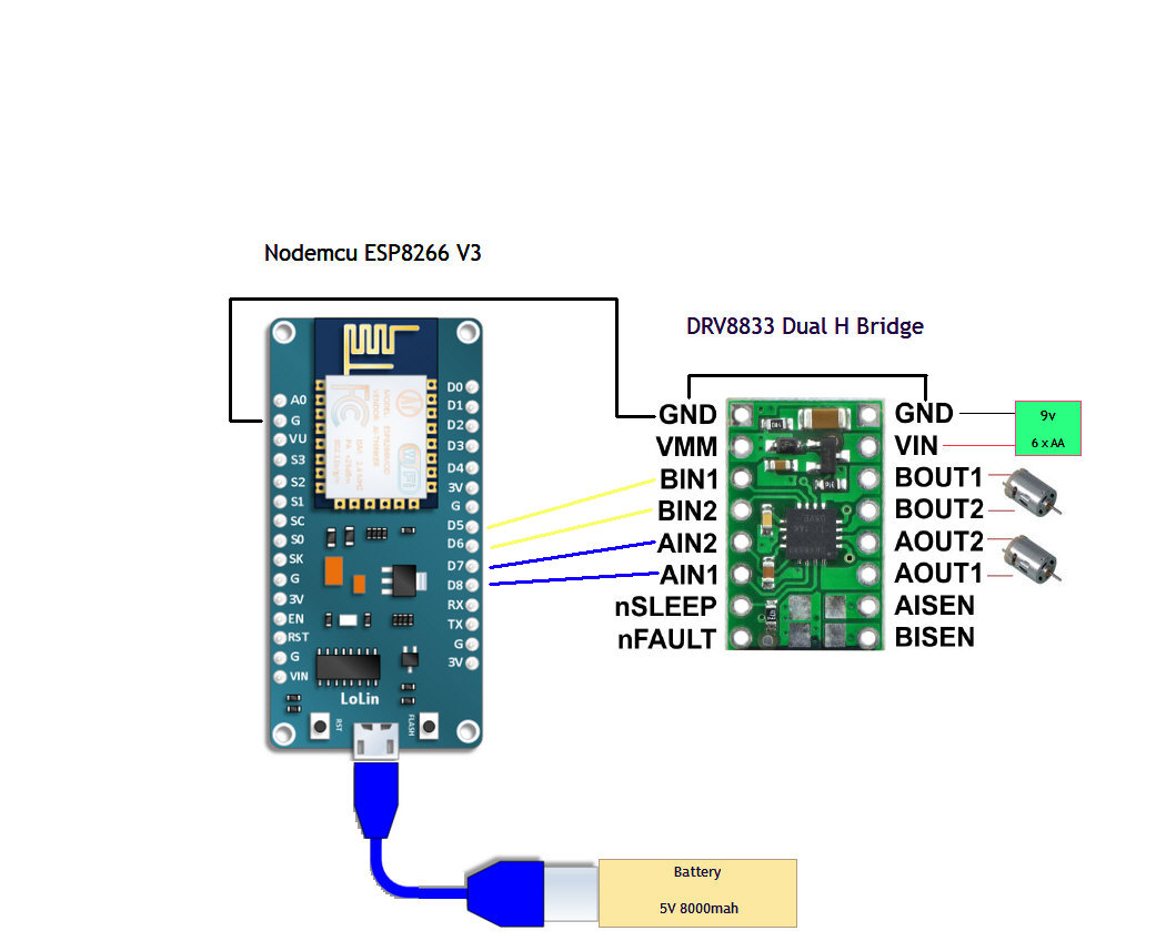
Can anyone help with this circuit to an RC car I am trying to make
Does this circuit look correct ? PLEASE help I am goin crazy here
I’m using ROBOREMO for Android APP to control by WIFI
Just wanted to know if I had this circuit correct first
Thank You,
John
#include <dummy.h>
#include <ESP8266WiFi.h>
#include <WiFiClient.h>
#include <Servo.h>
#include <SoftwareSerial.h>


const char *ssid = "SHEBLING2";  // You will connect your phone to this Access Point
const char *pw = "88956421"; // and this is the password
IPAddress ip(192, 168, 0, 1); // From RoboRemo app, connect to this IP
IPAddress netmask(255, 255, 255, 0);
const int port = 9876; // and this port


int FWD = 14;
int REV = 12;

int R = 13;
int L = 15;


WiFiServer server(port);
WiFiClient client;


char cmd[100];
int cmdIndex;

void execmd()


{ if(strcmp(cmd, "FWD 0")==0
 ) digitalWrite(14, LOW);

  if(strcmp(cmd, "FWD 1")==0
 ) digitalWrite(12, HIGH); }


void setup() {

  delay(500);

Serial.begin(115200);

WiFi.softAPConfig(ip, ip, netmask); // configure ip address for softAP
  WiFi.softAP(ssid, pw); // configure ssid and password for softAP

  server.begin(); // start TCP server

  Serial.println("ESP8266 RC receiver 1.1 powered by RoboRemo");
  Serial.println((String)"SSID: " + ssid + "  PASS: " + pw);
  Serial.println((String)"RoboRemo app must connect to " + ip.toString() + ":" + port);

}

void loop() {


  }
It sounds like you might be trying to control the DRV8833 board with PWM signals meant for hobby RC servos. The DRV8833 does not work with those kind of signals. You might look at the H-bridge logic table in the datasheet for the DRV8833 (which we link to on the Resources tab of the board’s product page) for more information about how to use the xIN1 and xIN2 pins on the board to control the state of the output pins.
From the POLOLU product page for the DRV8833 it says:
. Each of the two motor channels has a pair of control inputs, xIN1 and xIN2, that set the state of the corresponding outputs, xOUT1 and xOUT2; pulse width modulated (PWM) signal can be applied to each of these inputs. The control inputs are pulled low internally, effectively disabling the motor driver outputs by default. See the truth tables in the DRV8833 datasheet for more information on how the inputs affect the driver outputs.
However, my sketch does not use PWM I just want to turn on or off 1 DC motor right now at full speed
after I see that work ideally to control 2 DC motors with FWD and REV at full speed,
Thanks for your help, do you have any ideas why my sketch doesn’t work ?
The picture appears to be wired correctly for that code. You might use a multimeter or some LEDs to determine whether your microcontroller is toggling those pins high and low appropriately. If you post pictures of your setup, including any soldered connections you made, I can look for any obvious problems. Do you have a datasheet or any detailed specifications available for the motors you are using?