DRV8825 Waveforms

Hi All,
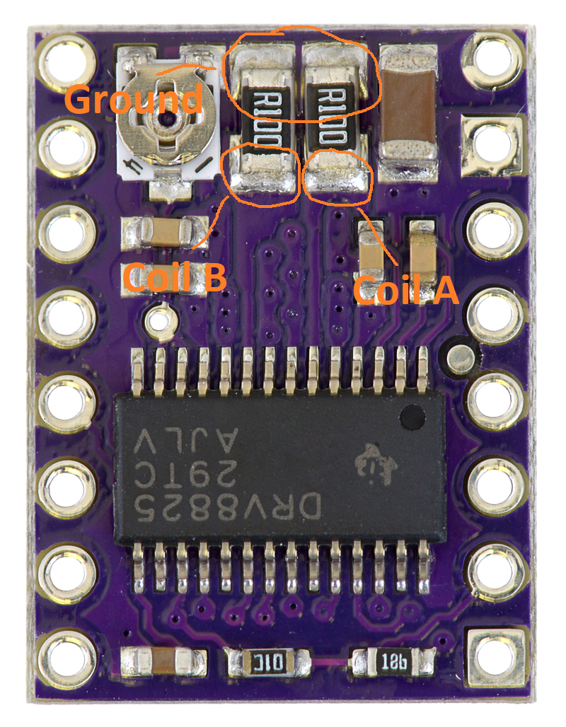
Currently working on a uController project and using the DRV8825 to drive a stepper motor in full-step down to 1/32 step modes.
The motor is a 4 wire bipolar, nema 11, 1.8 degrees, 8V, 0.67Amp (motor current limit is set, input signals are 3.3V and the motor supply is 24V)

The motor runs, not a problem there… but I noticed it was a little ‘choppy’ in microstep modes - ie: not as smooth as I thought it would be (I also run several Gecko drives elsewhere in uStep mode and are perfectly smooth)
I connected a DSO to check the wave forms (with NO MOTOR LOAD connected) and here’s what I have found -


This is 20 PPS, in Full Step mode. Yellow trace is the step input, Green trace is one leg of the motor coil (output 1A). Pretty much what I would expect to see


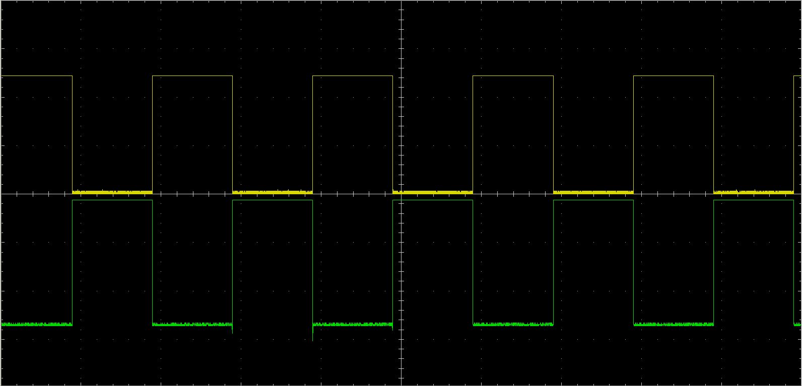
Here’s the result of Full Step with the DSO on the 1A and 1B Outputs. Again, nice and clean


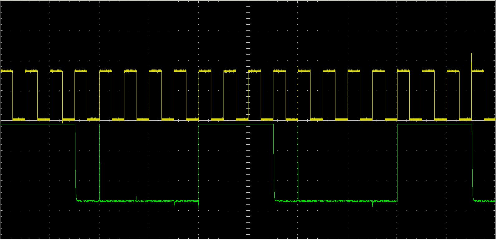
This one is the same conditions (in/out), but running in Half-Step mode. It seems now that I’m missing a third of my motor driving output (which is now in the form of a sharp pulse)


Again, the same output conditions, but the result of the half-step setting…

ALL microstepping modes have the same resultant waveform.

Is this normal or am I missing some setup parameters? I would expect to see a clean output waveform right across the stepping modes (the only thing to change would be the input pulse count to the output frequency)

So, is there something I should be looking at or is this what is meant to be?

Testing the driver without a motor attached will not be very useful and generally, it is the current through the coils that is important, not the voltage the driver applies across them. With that motor, an 8V supply applied across the coils would produce 0.67A of current. With your 24V supply, a current limiting stepper driver like the DRV8825 should be switching on and off rapidly (at about 30kHz) to step the 24V supply down to produce 0.67A current through the coils. The driver itself monitors the voltage across a current sense resistor and adjusts the duty cycle of the PWM to get the specific target current. When microstepping, the target current varies with the microstepping position. If you do not have a load attached to the output pins, there is no current, so the driver would just turn on in the appropriate direction.

To get a good sense of the current (if you do not have a current probe for your scope), the best thing to measure would be the voltage across the current sensing resistors (shown in the image below) when the motors are attached. Looking at the sense voltage for the current waveform might show if the choppy motion you see is due to missed microsteps and, if that is occurring, we might have some suggestions for reducing it. Also, how fast are you stepping? Could you include the voltage and time scales for any scope captures you post?

-Nathan

Hi Nathan,
Thanks for your help… I know that the REAL proof is in running with a motor connected, but I was just interested in waveform shapes at the time. I only thought it a little odd that there was a tiny glitch in microstepping modes.

So, first up, it all seems good this morning - I took the card out of circuit and soldered a couple of tails on the resistors to get my DSO probes hooked up. When put it back in (just to be sure), I re-adjusted the vRef.
All hooked up and running, here’s my results -


Top Trace is Coil-A and bottom Coil-B… Timebase is 1ms/Div and the levels are 50mV/Div.
This is 1200Hz running in full step mode
To me, it looks pretty close to identical waveforms, 180 degrees apart (What I would expect to see)


Again, top is Coil-A, bottom is Coil-B with the same DSO settings.
This is 1200Hz running in half step mode
Again, near enough to identical (With the only difference I can see the bottom is a little ‘spikier’ - but that will only be the CRO failings - a cheap PC based one from e-bay. Proved that by hooking both probes to the same point with the same spiky difference)

Testing down to 1/32 mode, the wavforms are all the same in comparison - all 180 degrees apart,

I don’t know what the wave form is supposed to look like, but I’m happy that BOTH coils are showing the same.
That’s good enough for me, and it’s running pretty smooth now :slight_smile:
My guess is that my Vref was probably a little out of adjustment

Again, thanks Nathan!
John

Thanks for posting those scope captures. You should keep in mind that there is a reversal of the current direction through the coil between the cycles shown in those measurements, but since the reversal happens in the H-bridge, it does not show up on your scope and the coil waveforms are actually 90 degrees apart.

The DRV8825 sometimes has troubles operating low voltage coils (which also have relatively low inductance) in slow-decay cycles, but your motor seems like it shouldn’t have that problem and the scope captures seem to indicate that to be the case as well. I’m glad to hear it is running smoothly.

-Nathan