I am working in a project in which I am controlling a NEMA17 stepper driver, controlled with a DRV8825. Due to my velocity needs, I am supplying 41.5V to the drivers approximately (it comes from a battery so the voltage level can change).
When running my system, everything works correctly, but when the driver reaches a certain temperature, the overheating system turns off and on the driver since the temperature reached is above the limits. This makes clear that my system needs some kind of dissipation.
In order to test the consumption of each of the motors, I have measured the current provided by the power supply to the drivers. I measured 0.15A, so a total of 6.2W are being provided to the driver.
On the other side, if I measure the voltage and current on the motor’s phases, I obtained that for each phase, 1.5W are being provided to the motor (2V x0.75A), so a total of 3W (1.5Wx2) are being supplied to the motors. Subtracting this to the total power given by the power supply, I realized that approximately 3.2W are being dissipated by the driver as heat power.
I was wondering whether it would be a better option to locate a heatsink on the top of the driver or on its bottom, since there’s a metallic plate where thermal vias are located. I couldn’t find out if there’s an optimal place to locate it since I could get the thermal information of the chip but not from the carrier, so I don’t know if more heat is being dissipated from the top or from the bottom.
I moved your post to the “motor controllers/drivers and motors” section of the forum since it is more appropriate here.
We do not have much specific advice when it comes to adding heatsinks to your project, but my general expectation is that attaching a heat sink directly to the driver IC will probably be more effective. If possible you could also just attach heatsinks to both of the locations you mentioned. You might also consider if you can implement some type of forced airflow (e.g. a fan).
Thanks for your response.
I’ve been monitoring the temperatures on the driver both on the top case and on the lower dissipation plate. Surprisingly, I am measuring similar temperatures at both sides.
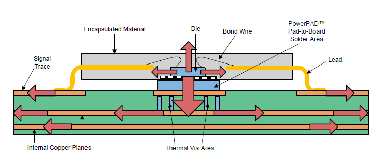
I was expecting to obtain higher temperatures at the bottom plate since (as TI explain in their datasheet) this driver should dissipate most of the heat through its thermal vias. See picture below.
Thus, since most of the heat should be dissipated through the bottom plate, this part should be getting much hotter than the top case of the driver. Is this behaviour normal?
As this driver uses the PowerPAD package from TI, I was expecting the thermal resistance from junction to bottom plate to be way lower than the thermal resistance from junction to top case. Is this true?
Maybe the carrier isn’t designed following the package recommendations from TI in order to improve the heat dissipation through the thermal vias.
It doesn’t seem unusual to me for the chip and pad to be around the same temperature. Even though the PCB is probably drawing more heat out of the chip than what is being dissipated from the top of the chip, the PCB itself is also dissipating that heat at a greater rate, so I would not necessarily expect the PCB to heat up more than the top of the chip.
It looks like you might have found that diagram in TI’s PowerPAD Thermally Enhanced Package application note. That note assumes a 3" x 3" board, so I expect our much smaller design to have fairly different thermal behavior, but we designed the board to make the best use of that area and connect as much copper as possible.