I`ve got the strange situation which I do not understand.
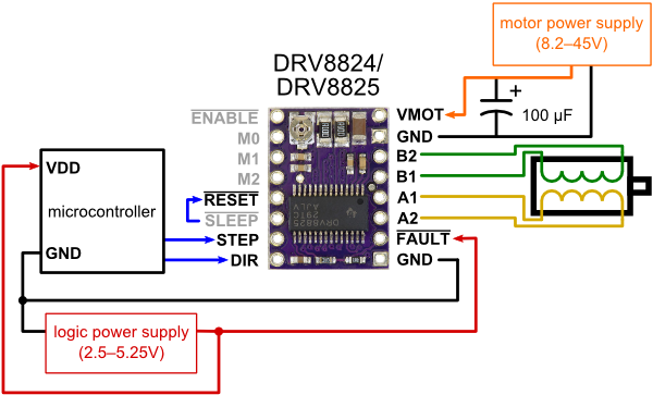
I have two steppers (0.4A, 24V, 60Ohm per coil). Each stepper is connected to DRV8825. Motors have common power supply (24) and common ground. Both drivers are connected to the same micro controller (same 5V logic level, same GND). Drivers logic, motors and micro controller have common ground. The scheme is attached.
The problem appears when I switched off one motor (logically, by the command on pin ENABLE of DRV8825). Suddenly, I see that current level fall down on both drivers. I check power supply (5V and 24V) - OK.
So, complete situation represented on the second screenshot:
S1: both motors are switched on
S2: first motor is switched on, second - switched off
S3: both motors are switched off
S4: second motor is switched on, first - switched off
S5: both motor are switched on
Also I hear that current is changing by the sound of motor.
The motors are connected in parallel… One motor, 60 Ohm. 24V → 0.4A. Two motors, 30Ohm (in parallel), 24V → 0.8A. Should be OK…
So, why does the current fall down on the second motor when I switched off the first?
Currently I decided to keep motors powered all time, but interesting to know… Looks like I miss something simple.
Where are you measuring the voltage shown in your graph and what are you using to measure it? Is it the VREF via on the motor drivers? What kind of power supply are you using?
The description of the power supply I use you can find here
To be honest, the power supply is of low quality. 24V and 5V is OK, but 12V output is bad (unstable, has some vibration ~0.2V-0.5V). So, I do not use 12V output. 24V output is connected to motors, 5V output to 5V on drivers and micro controller.
I do not see any thing wrong with your wiring diagram. If you post pictures here that show your connections, I might be able to spot something that looks suspect. Does it behave the same way if you disconnect your motors? You might also try simplifying your setup to see if the behavior changes.
If you mean photo - I think it useless, because of many wires.
If I disconnect my motors, the behavior is completely different: the current is in the low level like on the stage S3 always (like both motors are switched off logically). Switching On and Off logically makes nothing.
I made test with another one device (almost the same design, just some extra sensors and another remote control) - exactly the same result!
About your advice to simplify the design… The remote control is disconnected. What else? I can disconnect GPS sensor and Bluetooth HC-06 module, RTC and LCD, but has no any relations to motors… Its connected to Serial or I2C and powered with 5V continuously…
The control inputs should not have any influence on the VREF voltage. Also, the driver ICs have independent circuitry, so there is no reason the VREFs should influence each other. On one of the boards in my office, VREF only changes if I drop VMOT below its operating range. Is there a different power supply you could try?
Could you connect one of the boards according to its minimum wiring diagram and then test it by manually toggling the enable pin with a jumper wire to see if VREF changes?

