
I’m currently using a DRV8825 to try and drive a 42×38mm NEMA17 stepper motor (#2689). However current limiting Vref is not acting as expected when the potentiometer is turned and I am unable to get any output from the driver.
I only needed to use the full step mode so I wired the driver up to an arduino uno and a variable power supply at 10V according to the wiring diagram on the DRV8825 description page. I currently have the 5V logic side sourced from the arduino’s 5V pin and a common ground between the motor and logic sources. The DIR and STEP pins are connected to the arduino’s pins 8 and 9 respectively so that I can use the DRV8825’s arduino library.
Here is an image of my setup. Note no motor is connected as I was just checking the driver’s output with an oscilloscope (the probe can be seen in the lower right corner).
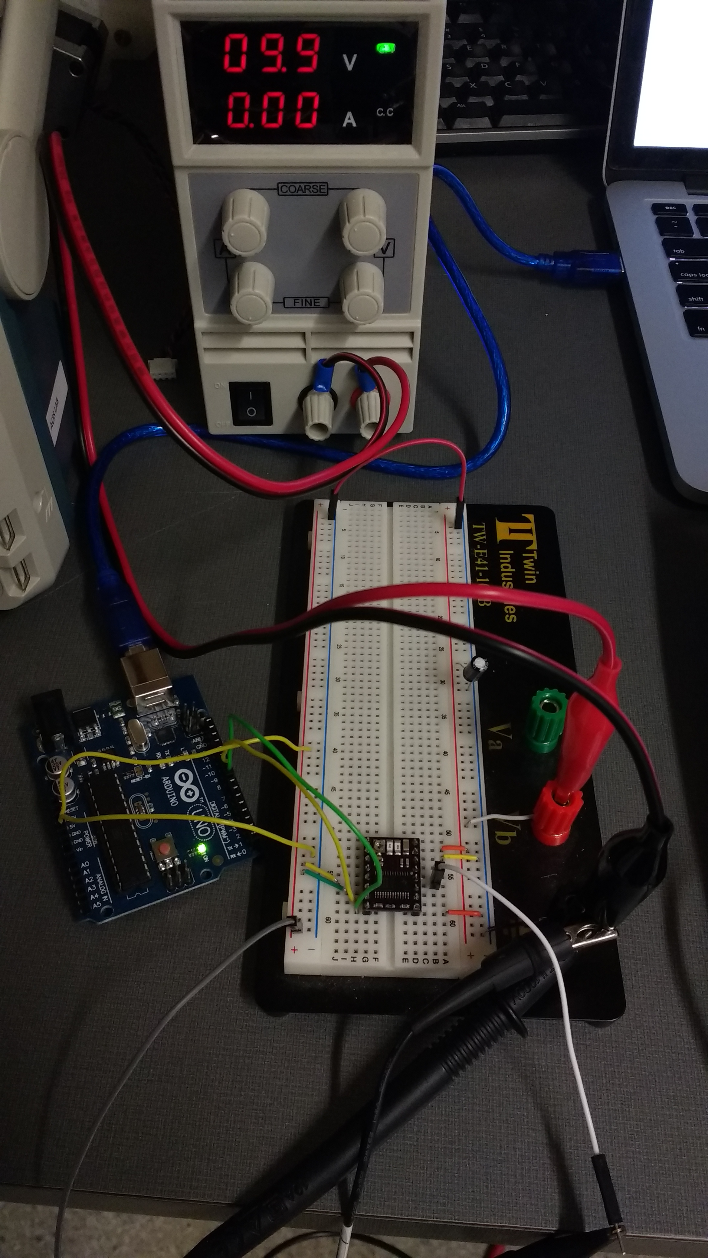
Given that the motor I’m trying to drive takes 2.8V, I attempted to set the current limit according to the product guide. I turned the potentiometer 3-4 rotations clockwise and counterclockwise but could not find it’s limit - it just kept on turning in both direction for with no resistance while the vref alternated between 0V and ~150mV. This seems pretty suspicious but eventually I left the vref at ~150mV and moved on to see if I could get any output from the driver.
When running some slightly modified example code from the DRV8825’s arduino library I can see 15us pulses on from the arduino on the STEP pin, but nothing from any of the driver’s outputs.
Here’s that arduino code:
(BasicStepperDriver-example.ino (597 Bytes)