Hello, I have 2 drivers DRV8825 and TB67S249FTG connected with Nema17 stepper (model 17HS1401 12v 1.3A). Problem is that neither of those drivers do not work as expected. Stepper motor only vibrates, or slowly moves to one direction only and skipping steps. I have tried to do the following steps:
swap the 4 wires between the driver and motor, no help
adjust the current limit, if it is the minimum, stepper motor is silent, in the max position motor just vibrating (DRV8825) or moving slowly and skipping steps (TB67xxx). Drivers get very hot and also my motors get very hot after about 1 minute powering, even when I am not trying to step. I have shut down power.
tried to use different stepping modes full step 1/2 etc., motor tries to make half step only, showing that my drivers should functional (not burned)
tested also 3 different steppers, but the behaviour is the same
Power source is LIPO 3S giving 12V, also using L7805 regulator to get 5V for the logic power.
My schematic is like suggested in the documentation of the drivers, with capacitors etc.
(I can show my schematic, did not find a way to insert PDF file here)
I am using Arduino Nano RP2040Connect, dir and step pins connected to A2 and A3.
I can show my code, but the same problem can be demonstrated without Arduino, just connecting 5V to dir and step pins.
What else should I test to make it working ?
Can you post some pictures of your setup that show all of your connections, including close-up pictures of the top and bottom sides of both stepper motor drivers?
Keep in mind that setting the current limit on your driver too low will mean that your stepper motor is underpowered, and although it is normal for the motor and driver to get quite hot during normal operation (even while just holding position), setting the current limit too high could damage your stepper motor. So, it is important to set the current limit appropriately. For testing, please set your current limit to match your motor’s rated current (1.3A). On the DRV8825, this corresponds to when VREF equals 0.65V. On the TB67S249FTG, this corresponds to when VREF equals 1.04V. Try to get as close to those values as you can, and make sure not to get them mixed up with the wrong driver.
By the way, you can attach files (like PDFs) to your posts by using the upload button. Alternatively, you could just drag and drop the file into the post’s text editing window.
stepperschema.pdf (28.1 KB)
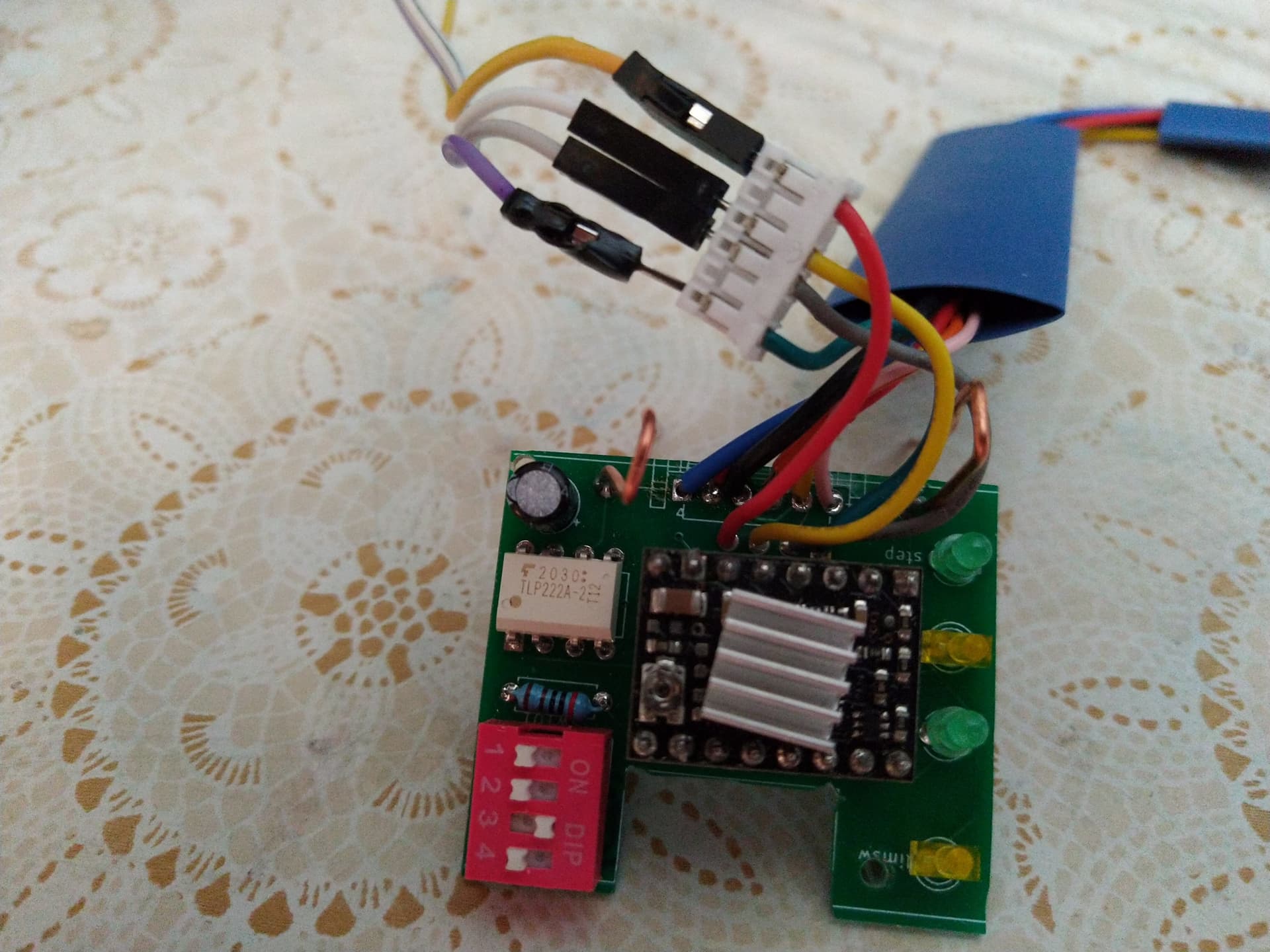
Here is a picture of my little PCB, I am going to attach it near the stepper motor itself.
Also the schematic of this PCB. There is 6-pin JST connector attached to Arduino board (pins GND,VIN=12v,regulated 5v,step A2 Arduino, direction A3 Arduino,limit switch).
There are LEDs indicating power,step and dir, all leds blink correctly when trying to drive the stepper. The 4 pos DIP switch: 1-3 are M0,M1,M2 control and 4 sw gives power to DRV8825 logic. So 4 must be on with 8825 and pin 3 on with TB67x driver for full step mode. TLP222A is a solid state relay, I am using Arduino Nano RP2040Connect. It gives 3.3V output for pins, but drivers step and direction pins get 5V.
I have also tried to connect +5V direct to the driver pins but the stepper motor only vibrates (goes one step forward and then returns back for every rising edge +5v for step pin)
My stepper motor max current is 1.3A and 8825 max is 1.5A TB67xx max 1.6A, so setting limit to the maximum, does not burn the stepper ? Does that vibrating behaviour indicate that the motor get too much or too little current ? I have also tried to measure the coil current directly, that is about 0.6A standby without stepping action.
Setting the driver’s current limit to the maximum possible value can damage your stepper motor. It also risks damaging the driver (or at least making it unreliable) since it is possible to set current limits higher than what the drivers can continuously handle causing it to trigger it’s thermal shutdown. Can you set the current limits on your drivers to 1.3A value as I recommended and let me know how that makes your stepper motors behave? Also, some of the soldering looks like it might be problematic, though it is hard to tell just from one angle. Please post some close-up pictures from other angles as well as pictures of the bottom sides of your boards.
There are several factors that could cause the vibrating behavior you described. The current limit being set incorrectly is one possibility, but it could also be caused by the load being too high or even something like the coils being connected incorrectly. Could you post a picture that shows your connections all the way to your stepper motor, and if you have not already, try removing anything attached to your stepper motor to see if the behavior is the same when no load is connected?
By the way, both the DRB8825 and the TB67S249FTG are compatible with 3.3V, so connecting those directly to the I/O on your Arduino Nano RP2040 Connect should be fine.
Hello, thanks for your help, I finally got this working. Setting the current limit (TB67S249FTG) is really tricky. If VREF is say 0.8V and you slightly turn the pot cw, VREF jumps to about 1.2V. But the real issue here was the wires between motor and the driver.
There are 6 pins in the Nema17, pins 2 and 5 are not used, but pins 1 and 4 is one coil pair, and pins 3 and 6 the second pair (I measured the resistance between pins). I would expect that pins 1 and 3, 4 and 6 would be coil pairs.
Anyway motor steps now using both drivers, but TB67xx is heating , while DRV8825 temperature remains quite low when powered on.
I am glad to hear you got your stepper motor system working! Thanks for letting us know.
It sounds like you are using a six-lead unipolar/bipolar stepper motor. For future reference there is guidance for how to connect those and other kinds of stepper motors on each of our stepper motor driver product pages under the FAQs tab. For example, here is a link to the DRV8825 carrier’s FAQs tab