I have a problem with DRV8825. When I turn off my signal generator and the FAULT pin is connected to ground, the Ampere-meter indicates the normal consumption current (< 0.2 A). But as you know in this case the DRV8825 does not work. Because the FAULT pin must be connect to VCC. However, when I connected the FAULT pin to VCC, the abnormal consumption current is showed by Ampere-meter (> 2.8 A). It should be noted that when I turn on the signal generator, every thing is okay in this case.
In other words, I must connect FAULT pin to VCC to drive DRV8825, what should I have done that the consumption current is became reasonable in this case?
I am sorry you are having trouble with your DRV8825. A stepper motor will draw the most current when it is holding its position, so what you described sounds like normal behavior. However, that current draw seems a little too high for that stepper motor driver. Can you tell me more about your system? What do you have your current limit set to? How are you supplying power? What stepper motor are you controlling? Can you post pictures that clearly show your connections and how you are measuring the current draw?
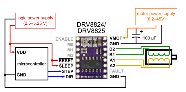
In picture 1: the SLEEP and RESET connect to each other and then connected to VCC. Moreover, FAULT pin dose not connect to VCC.
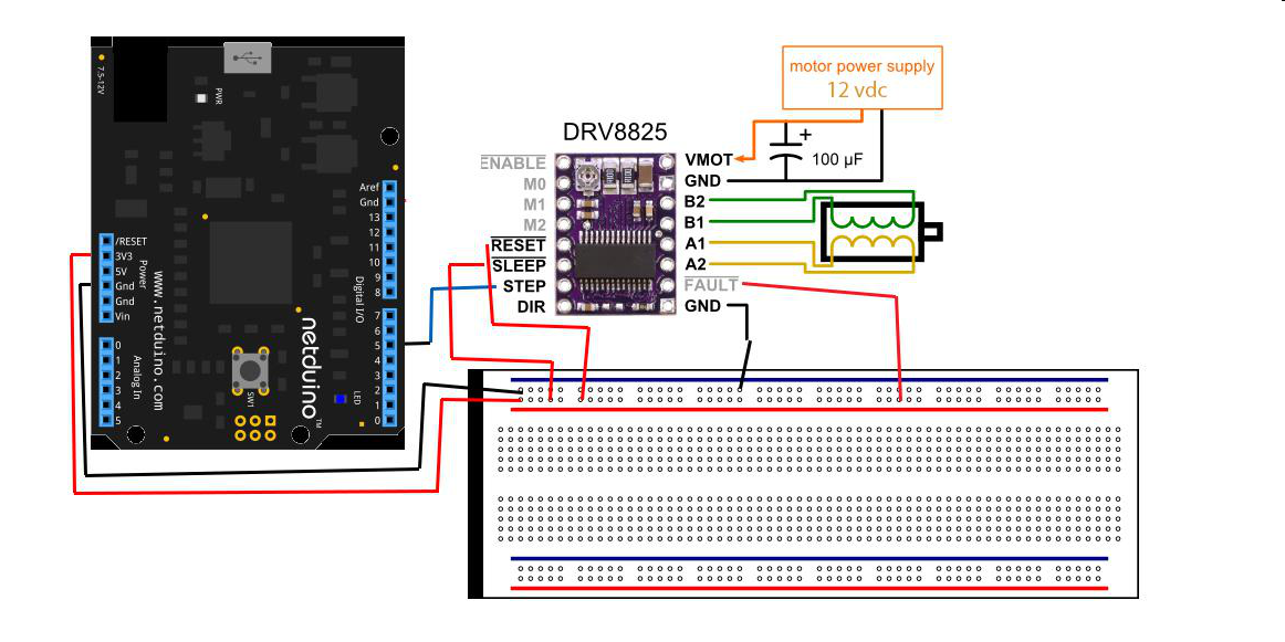
But in Picture2: the SLEEP and RESET connect to each other and but does not connect to VCC. Moreover, FAULT pin connect to VCC.
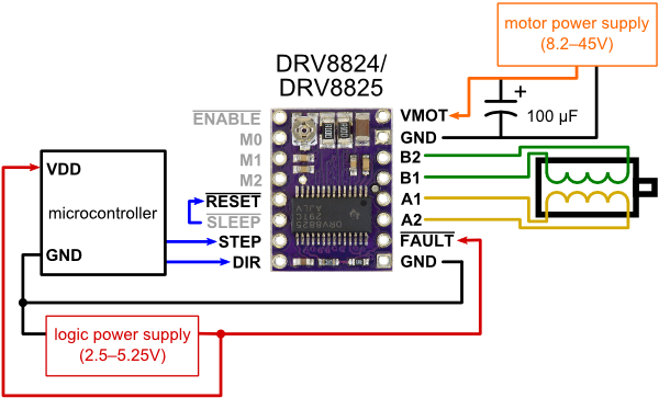
But in Picture3: The SLEEP and RESET connect to each other and then connect to VCC. Moreover, FAULT pin is also connected to VCC.
when I test all mentioned wiring, all of them works. I want to know,
1-which of them is true and you suggest?
2- In all of them, when we turn off the signal general, the current draw seems high (>1.5 A). Specially in case 2. what should I have done?
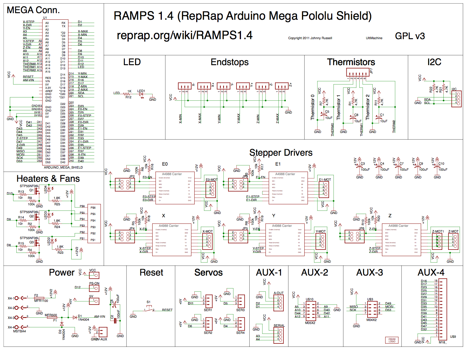
We designed our DRV8825 carriers to be drop-in replacements for our A4988 boards, which also means that the minimum connection diagram for the A4988 is a valid alternate way to connect the DRV8825 to a microcontroller as well. You can find those two valid minimal connection diagrams on the DRV8825’s product page. It looks like the connections your RAMPS kit uses is similar to the minimal diagram that works for the A4988. As for your third picture, we do not expect anything bad to happen when nFAULT, nSLEEP, and nRESET are all connected to logic high.
As I mentioned before, stepper motors will draw the most current when they are holding their position. So, it makes sense that the current drawn from your stepper motor is high during the times your signal-generating device is off. In general, the current drawn while the motor is holding its position will vary depending on what microstepping mode and which particular step it is in. So, if you are using microstepping, that might explain why you get different current draws when stopping the motor at different times.
