Hi,
I am using drv8825 to drive a stepper motor. What i noticed was the motor is not rotating uniformly @ 0.45deg in 1/4 steeping. After some time of operation motor stopped rotating and just make hiss sound. While debugging i found that the motor connection A1,A2,B1 and B2 all are shorted where as there is no wiring short available on board, so i am suspecting the driver is killed. I was applying pulse to Fstep(pin of drv8825) once in every two seconds. The ON time of the pulse was 2micro seconds. Is it okay that all motor outputs are shorted, though it is not physically shorted?
Can anyone suggest what could have gone wrong?
Vref=0.5v
Motor Supply =12v
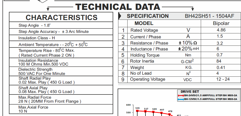
Motor Specification:
Thanks in advance.
Hello.
How did you measure that short? In general operation, we would expect the driver to have some period of time where all of the output pins are connected to ground at the same time. Can you post pictures that show your board and how everything is connected? That ON time for your step pulse is just barely longer that the minimum required for the driver (1.9uS) and things like stray capacitance in your circuit could easily cause an issue. Why are you using such a short time?
-Nathan
Hello nathanb,
Thanks for reply. Once motor stopped, then i used a multimeter to check for short, after turning OFF motor and driver supply.
Circuit connections are same as given here https://www.pololu.com/product/2133.
The ON time i selected based on minimum requirement specified in drivers datasheet. Since i am using stepper for first time i want to know How increasing ON time will help as anyway driver will maintain the phase current after pulse is turned Off? Is it like current in motors phase will reduce and comes to zero after pulse is turned OFF?
Also i wanted to know what driver would do in the case of motor stall?
Thank you.
Stepper motors require current through the coils to maintain holding torque when the rotor is stopped/stalled. The buzzing you mentioned in your first post indicates that the driver is sending current through the coils. If you do not send a valid signal to the STEP pin, the driver will continue to hold the rotor at the same position.
Varying the width of the step pulse does not make the driver behave differently, but pulse widths that are right at the limit are more likely they are getting distorted and then not read correctly by the driver. Can you try sending 1ms pulses? If that does not make the motor move, can you send pictures that show your board and connections including any soldered connections you made?
-Nathan