
Hello,
I have some questions about your PCB ‘DRV8838 Single Brushed DC Motor Driver Carrier’. I want to use it to drive a solenoid. In the DRV8838 datasheet (http://www.ti.com/lit/ds/symlink/drv8837.pdf) in section 8.2, figure 10 only recommend using two capacitors of 0.1 uF Then, what functionality does Q1, D1, R1, R2, C1, C2? (https://www.pololu.com/product/2990/pictures#lightbox-picture0J5757)
Another question, is JP3 a via to join ground planes? Thank you.
Hello.
Q1, D1, and R1 form a reverse voltage protection circuit and JP3 is a point to test that circuit. C1 and C2 are decoupling capacitors and the values for decoupling capacitors can vary from the reference design depending on the other circuitry the IC is used with. We use a larger capacitance since it is possible our customers might use long power leads. R1 is a damping resistor to limit the current into and out of C1 to help limit destructive LC spikes.
-Nathan
Hi Nathan,
I’m using a DRV 8838 to drive some small latching solenoids (https://www.takano-sanki21.com/sanki/en/products/optical-shutter/BOS10/15/), as described. I’ve had a few go bad, do I need to add some diodes to handle LC spikes, or is there something else I am missing here? Unfortunately, these are being used remotely so I can’t do I whole lot of testing onsite… covid stinks!
Thanks,
Nate
Hi, oddballvi.
It is possible that those drivers were damaged by LV spikes, though as Nathan mentioned there are some protections. It is hard to know what is going on without more information though. Do the bad drivers have any visual signs of damage? What are you using to supply power and how long are the power wires? Could you post pictures and a diagram that show the whole system with all connections?
-Claire
Hi Claire,
Thanks for responding! I am using an OTS Industrial AC-DC power converter to supply 5VDC for power, and driving the logic rails with a digital output DAQ from NI. Here is the wiring:
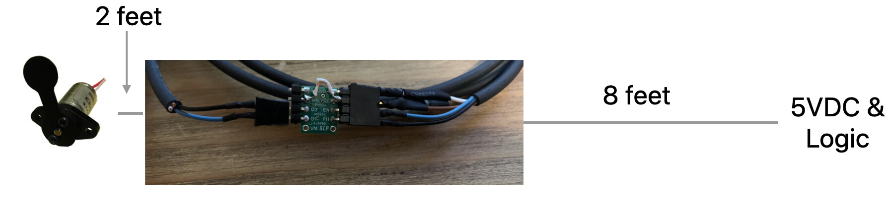
As you can see, I wired the VCC to the VIN in order to supply the logic power. Everything else is pretty simple.
If you’d like more details on the individual components, I could supply those as well. Thanks again so much for any help!
Nate
I do not see a connection between the ground on your DAQ and the ground on the driver. I am not sure that would lead to damage though. What was happening when the drivers broke (e.g. plugging in power, switching the direction of the solenoid, etc.)?
-Claire
Sorry for the delay here! The GND/5VDC supply on the DAQ come from a shared supply, so they should be good there. Are the 2 GND’s on the chip on the same net on the PCB?
Also, I’ve had like 6 of these blow up and I can’t figure out why. Any chance I could send you guys one to try and debug how I am blowing these chips up?
Both pins labeled GND on the board are internally connected.
Unfortunately, it is usually not practical to determine exactly what went wrong by just looking at a damaged board. If you tell me more about you system and conditions though, I might be able to help find the issue. Did all six boards that died have VIN and VCC connected? What were the drivers doing when they failed? How many boards total have you tried?
It looks like you are using a fairly low power solenoid, but it is possible voltage spikes from it are coming back to the VIN line. If they are higher than 7V (the absolute max for VCC), that could damage the driver.
-Claire