
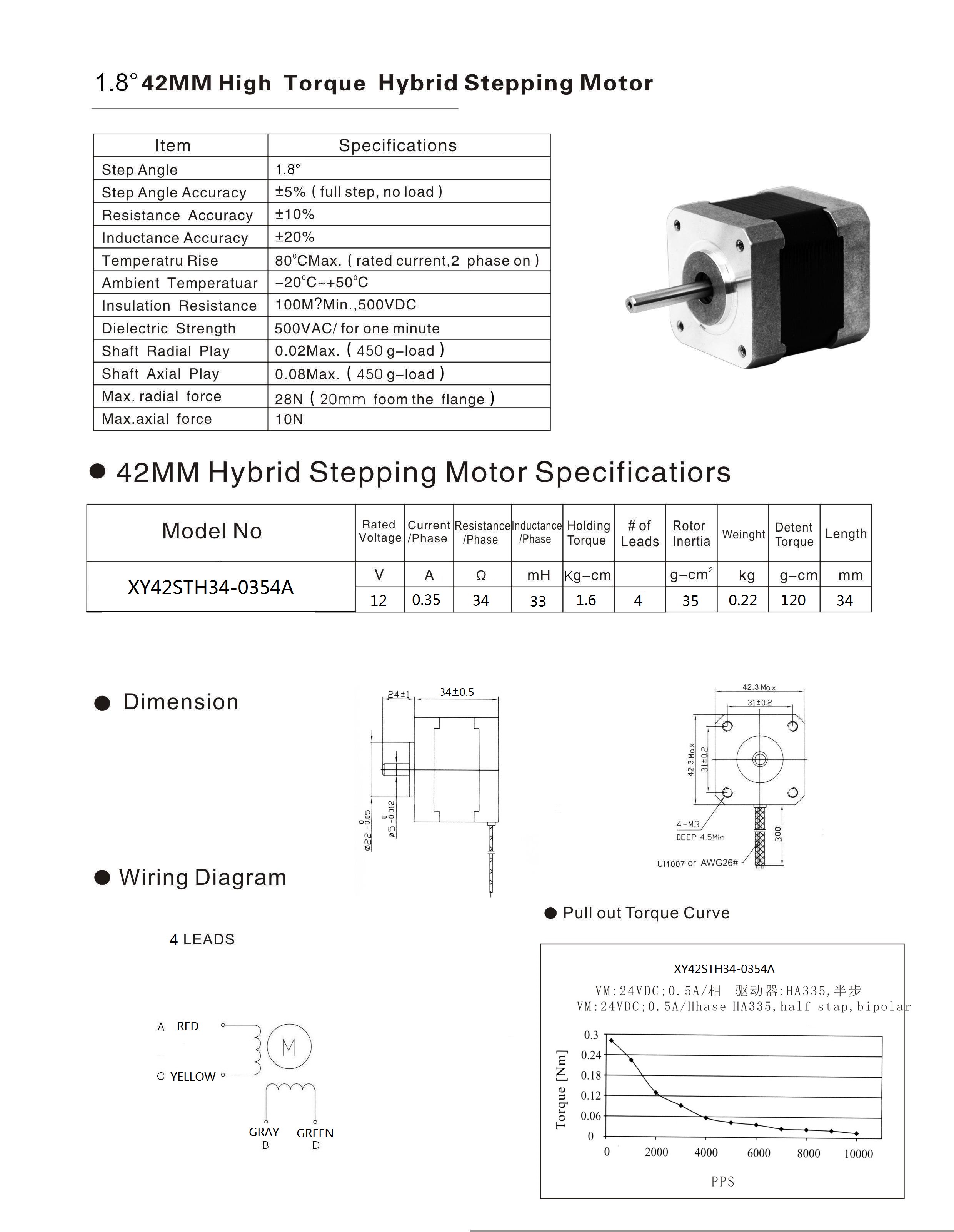
I have a NEMA 17 stepper with a Current/Phase of .35A.
I understand I need to “current limit” your A4988 with the tiny potentiometer. I have 2 separate power sources: a Raspberry Pi plugged into the VDD and GND pins to power the board itself and a 12V 2A motor supply plugged into VMOT and GND, with a diode, of course.
When I follow the video instructions and test the poten. itself (as REF), I ONLY get the voltage from the Pi (3.3V or 5)…I’m confused about the math. I would think the poten. would tune down the incoming 12V from my ps, not the incoming voltage from the Pi. Did I connect something wrong, or, is the poten. indeed supposed to be tuning down the board power (and then based on that, some magical things accordingly tune down the per phase amperage? I’m really excited to get my motor spinnin’; please help!
P.S. I also have the RESET and SLEEP connected together; I think I see that this…“enables the board”