Debugging TB67S249FTG issues

Hello!

I’m running into a brick wall getting my stepper motors to move using recently purchased TB67S249FTG stepper drivers. They will occasionally give the tiniest of twitches (ex. When turned on), but otherwise the motors are locked in place.

Quick caveat: I’m a professional programmer with very little hardware experience. Parsing schematics to actual wiring takes a while if there’s not a physical picture. But I’m learning! Apologies if my terms aren’t right, just let me know and I’ll upgrade my terms.

The players:
- TB67S249FTG stepper driver(s)
- STEPPERONLINE 3PCS Nema 23 CNC Stepper Motor 2.8A 179oz.in 56mm Bipolar
- Elegoo Arduino Uno
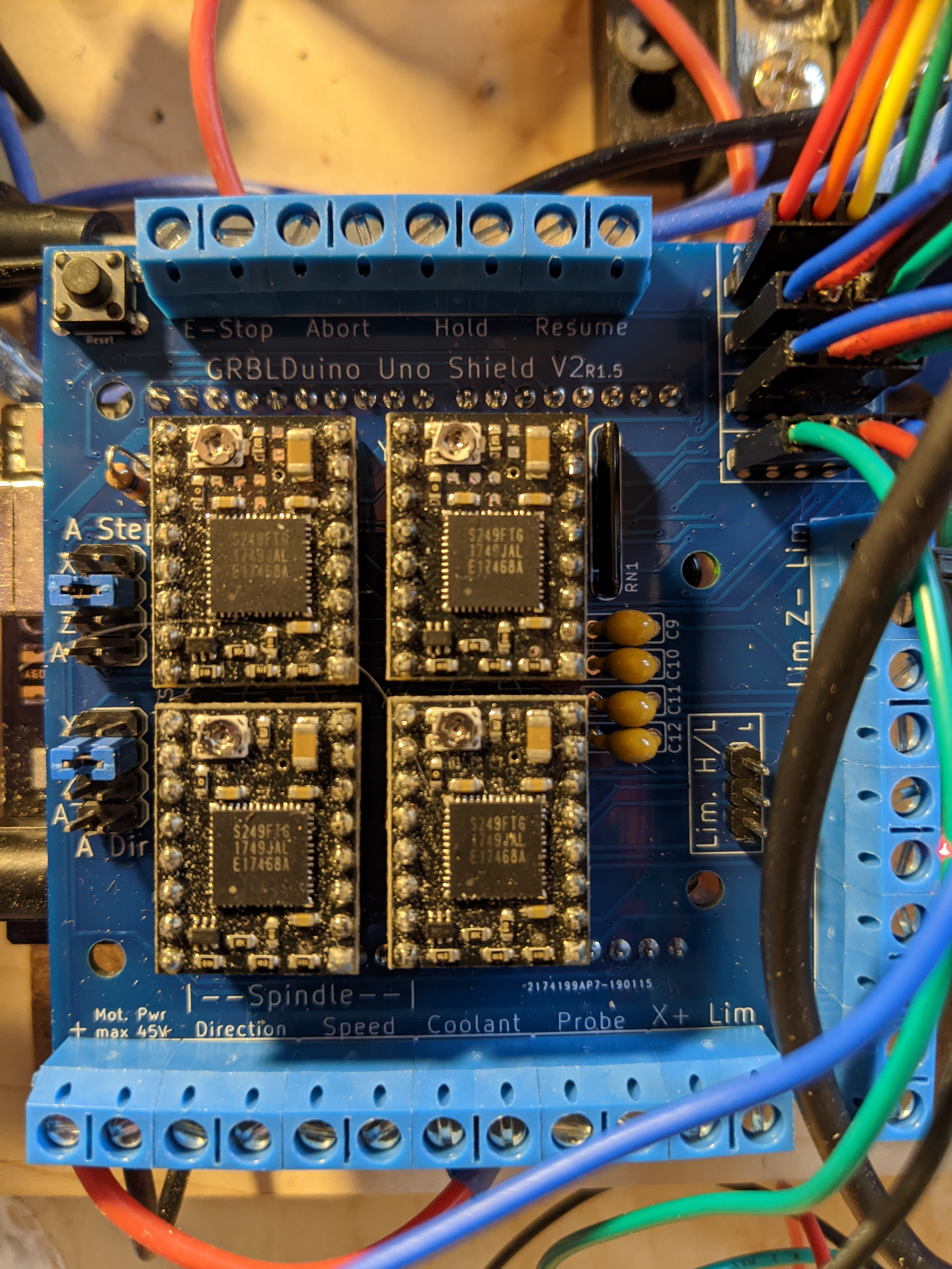
- GRBLDuino 1.1 from Eccentric Workshop running GRBL 1.1f
○ CNC Shield jumpers set for full step, I screwed up originally by having no jumper (Standby) after originally confusing DRV8845 spec with mine at the time. Whoops!
- 24v MeanWell power supply

In my software world, I’d try to rule out half the problems with a targeted diagnostic, then do the same on the result with another diagnostic, and repeat making the problem smaller until I found cause. I’m struggling to understand what those diagnostics might be in a hardware world.

So here’s what I’ve thought of so far, can someone help me fill in the gaps?

At rest, no commands sent or movement expected, multimeter voltage readings:
- VMOT Resting voltage to adjacent VMOT GND : 24V
- GND to FAULT : 5v
- GND to Enable : 0v
- OUTA+ to OUTA- , using multimeter to bridge pins and no motor: 24v
- OUTB+ to OUTB- , using multimeter to bridge pins and no motor: 24v

Other things which may or may not be useful:
- Send jog commands from CNCJS, no movement
- Send GRBL commands from PUTTY, no movement
- Circuit continuity (looks like a diode symbol on the multimeter? I think?) verified for both A and B on motor

How else can I track down the problem?

After weeks of trying to solve this or even just understand if this is broken, any help would be incredibly appreciated!!!
Dan

Hello, Dan.

We have two different TB67S249FTG stepper motor driver carriers, a compact carrier and a full breakout. Which one do you have?

Can you post a wiring diagram and some pictures of your setup, including ones that show all of your soldered connections? Also, what do you have the VREF voltage set to?

- Patrick

Patrick,
thanks for the response! I’ll add pictures that you requested in a bit, though I bought the stepper drivers with the header pins pre-soldered by Pololu. Would a picture of the full shield be useful? I’m happy to take pics, just want to make sure I’m not wasting your time.

Not sure if this fits what you are asking, but here’s the schematic for the shield that is using the driver:

FWIW: I started out working with that provider to make sure my wiring matched expectations on that side.

here’s the other info that you requested:
From the order: Item#3097 : TB67S249FTG Stepper Motor Driver Compact Carrier (Header Pins Soldered). If this isn’t what you are asking, it could help that my order # is 1J418761

VREF is set to 2.24 on all steppers (Motors are 2.8A)

Thanks!
Dan

Here’s the board with the stepper drivers in the middle. If I didn’t grab the right thing, just let me know and I can update with the correct angle/content!

Thank you for the information and picture. It looks like there is a ton of dust or something across your stepper motor drivers, but your shield looks clean so maybe there is just a focusing issue with your camera. Could you post some clearer close up pictures of the drivers? If they really are that dusty, I would suggest trying to clean that up. (If the particles are conductive they could be a shorting hazard.)

The compact driver can only handle up to 1.6 A without additional cooling, so your current VREF setting is way too high. Can you try adjusting the potentiometer so VREF is about 1.28V (which will correspond to a current limit of 1.6A on this driver)? That will limit the power you can get out of your stepper motor, so for troubleshooting your driver I would suggest removing any load you have attached to the motor or connecting a lower current stepper motor if you have one available.

If that does not resolve the issue, could you confirm that your drivers are in full step mode by measuring the voltages on the DMODE pins?

- Patrick

Patrick,

The particles are (non-conductive!) wood, probably leftover from making the drawer that the electronics are installed in. I went ahead and blew any loose pieces off with compressed air. Updated picture attached.

I didn’t think to mention it, but I’ve got 2 blower fans at 12v shooting air directly across the drivers. Picture of the closest one to the board is also attached. It may be difficult to see at this angle, but I’ve got the blower(s) raised up so the air goes directly across the drivers.

Also not pictured: for testing purposes, all motors are connected to my CNC shield without load, and are sitting adjacent to the electronics. FWIW, I do not have alternate motors to test with beyond the 4 currently in use.

Per your advice, I lowered the VREF on my Y-axis driver to 1.28V and tested for movement by issuing GRBL jogs via CNCJS. No movement observed.

I tested voltage DMODE0,DMODE1,DMODE2
For all 4 drivers:
DMODE0 = 0V
DMODE1 = 0V
DMODE2 = ~5V (actuals: 4.96V-4.97V)

Does this tell us anything? What shall I try next?
Thanks, again!!!
Dan

Patrick,
I definitely don’t want to derail the steps of your diagnostics, but I’m hopeful you may be able to include a quick idea on the following along with your response to my previous post.

Q: Is there a way that I could trigger motor movement without having to trigger it from a GRBL command? Just run a wire and and feed some voltage to a pin? I see a way to do this with the A4988, but I’m not sure it would work for this one AND I’m alsonot sure I understand the diagram well enough to be sure I wouldn’t accidentally burn out the driver in my relative ignorance. If the setup that is the answer to my question is not too complex, a picture of the physical setup I’m shooting for would help my confidence that I’ve done it properly.

Thanks!
Dan

Could you try measuring the nRESET pin to confirm it is measuring high? If it is, then the next step, as you suggested in your last post, is to try to simplify you setup so that we can test your drivers separately from your shield. The best way to do that will be to take your CNC shield out of the setup and directly connect a single motor driver at a time to your Arduino. You can use our minimal wiring diagram from the “Using the driver” section of the product page description as a guide for how to do that. Once you have that setup, can you upload a program to your Arduino that just pulses the STEP pin, like the one in this blog post? If that does not work, you could also try stepping the motor by just powering the driver, tying DMODE2 high, and manually touching the STEP pin to 5V repeatedly to see if it steps.

Also, if you have access to an oscilloscope, it would be good to use that to monitor your setup so you can confirm you are sending the signals you expect and see what is going on with the output.

If you have any concerns you are welcome to post pictures of the setup before you power it and I can let you know if it looks okay.

- Patrick

This is really great, thanks so much! I should be home in 90 minutes, will try then.

Would it be ok if I try your backup plan of manually checking the STEP pin to 5v first? That seems like something I could do in a few minutes while the driver is still in-socket? If that didn’t show anything, I could still reprogram the arduino and wire a stepper on a breadboard.

I don’t have an oscilloscope (yet!). I just got a logic probe, and was watching videos to try to understand if it would help in this case? What do you think?

Dan

Manually checking the STEP pin first would be fine, but please take the driver out of your shield before doing that. (Since we are not familiar with how your shield works, simultaneously connecting the driver to other voltages could potentially damage something.)

Can you share what specific logic probe you have? Most basic logic probes are probably not that much more helpful than a multimeter, but we cannot understate the value of an oscilloscope. A scope will save you a lot of time and give you better understanding of your systems, which enables better designs, better margins of operation, etc. Without one, you are left mostly just guessing about what might be happening, which is not a great way to operate.

- Patrick

Thanks Patrick,
Here’s my logic probe. Nothing fancy, just what a friend had and recommended
https://amzn.to/3dMB5eU
Thanks for the heads up on removing it from the board!
I’ll look into an oscilloscope.