Hello, I’m building a vinyl record cutter machine. I will drive the turntable with a belt connected to a motor. The motor speed needs to be precise, low noise and vibration. The controller would monitor and adjust the speed. The turntable will rotate at 2 speeds: 33-1/3 and 45 RPM. To create this the motor needs to spin at 396 and 540 RPM with my belt and pulley setup, and withstand 2.5 Kg-cm of torque.
I’ve initially selected these components. Do these seem like the best option or something else.
How would I program the 2 speed settings for the controller with feedback to maintain a precise speed and what would be a simple user interface to select one of the two speeds to use?
Thanks in advance for any guidance and suggestions.
It’s not clear if the torque requirement you mentioned is continuous or not, but please note that we generally recommend running our brushed DC gearmotors at 25% or less of the stall torque. The motor you listed has an extrapolated stall torque of 4.9 kg-cm, so your 2.5 kg-cm is well over that threshold. You might consider the 19:1 Metal Gearmotor 37Dx68L mm 12V with 64 CPR Encoder instead. However, please note that its free-run speed is only 530 RPM.
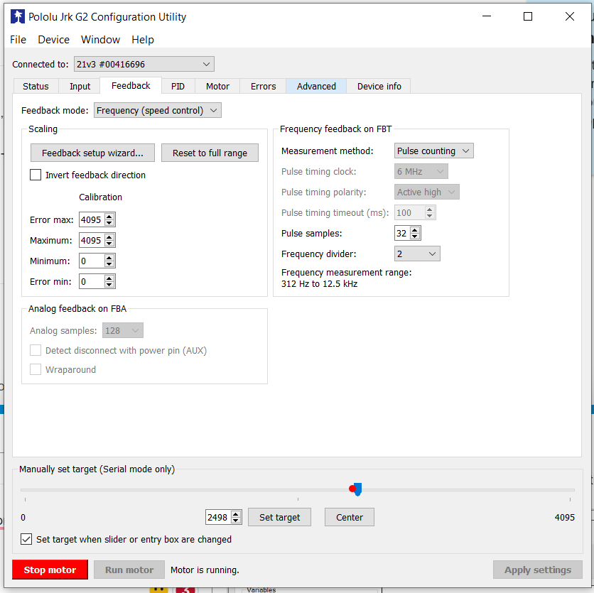
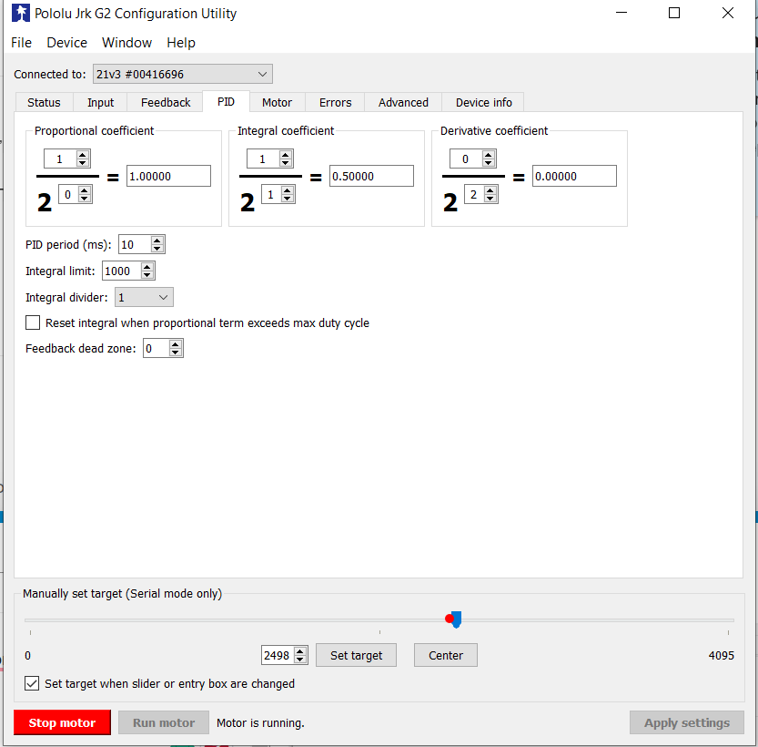
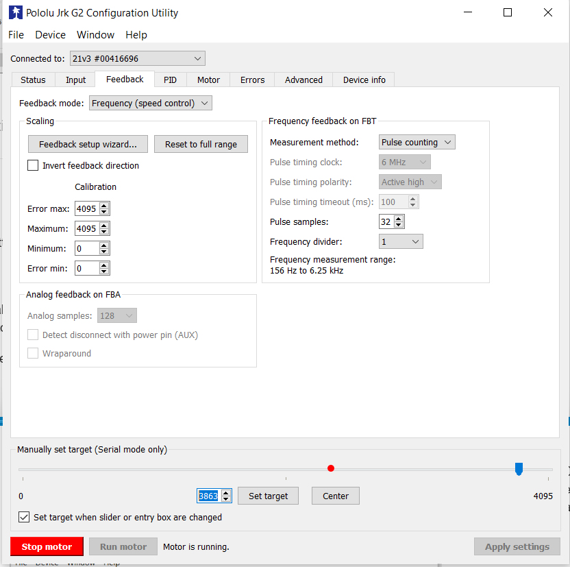
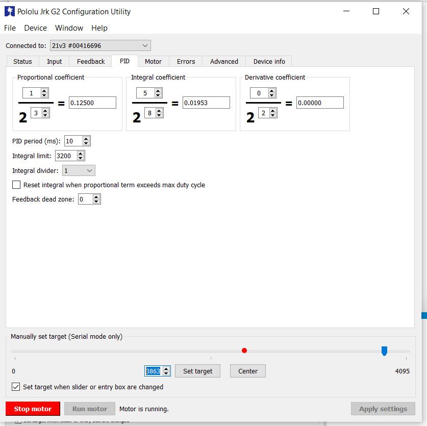
You can use that Jrk G2 controller to do closed-loop speed control for our gearmotors with quadrature encoders. To do that, you would first need to configure the Jrk G2 to use one channel of the quadrature encoder as tachometer feedback. You can find information for doing this in the “Setting up frequency feedback” section of the Jrk G2 user’s guide. Please note that his involves tuning the PID coefficients. Once all that is set up, you can use the Jrk’s set target command to specify the target value that corresponds to the RPM you want. You can send the commands using one of the Jrk G2 controller’s supported interfaces, including USB, TTL serial, and I2C. You can find information about the interface options in the “Setting up the control method” section of the same user’s guide.
Another option might be to use a stepper motor and Tic controller instead of a brushed DC motor. Because of the way that stepper motors function, it is generally easier to do precise speed control with them (it doesn’t require any feedback sensors), and they will last longer than brushed DC gearmotors.
However, please note that we have not characterized the noise and vibration of our motors. Depending on the stepper motor, driver, and how it is configured, it could be louder and cause more vibration.
Thank you so much Brandon. The torque of 2.5 kg-cm would be an upper continuous load. I forgot that this torque would be on the driven pulley and thus the driver pulley attached to the motor would be far less on the order of 0.2 kg-cm. I can also adjust the size of the pulleys to reduce the RPM needed from the motor to 500 or less and get either geared DC motor to work.
I like the idea of a stepper and controller and in fact I tried this with a NEMA 17, TMC2208 driver, and Arduino Uno, but I couldn’t get the speed higher than ~200 RPM not matter what I tried to change. I’m sure I had something amiss. Would you have a recommendation for which stepper and Tic controller for my application.
It is a little more difficult to judge the maximum speed a stepper motor can achieve since it depends on various aspects of your setup, but something like our #2267 stepper motor might be a good fit. You can look at the pull out torque curve in the datasheet to get a general idea of what the motor is capable of. The datasheet can be found under the “Resources” tab of the stepper motor’s product page.
We have a few options for stepper motor drivers that would work with that stepper motor. Our TB67S249FTG Stepper Motor Driver Carrier - Full Breakout and TB67S128FTG Stepper Motor Driver Carrier would both be good options since they can handle the current per phase rating of the motor continuously without any additional cooling. You could also consider the DRV8825 or MP6500 carriers, which can handle slightly less than the motor’s rated current (1.5A versus 1.68A). You can limit the motor to less than the rated current, but it will also limit the maximum speed and torque that it is capable of.
Thanks Brandon. I’m going to start with the DC motor with feedback. Which Jrk G2 board would you recommend? Would the 21v3 be appropriate for controlling speed with the 19:1 gearmotor with 64 encoder?
I should clarify that eventually I want a switch to set the speed to either 33.33 or 45 RPM and not have to reprogram the board to change the RPM. If this changes what control board I need.
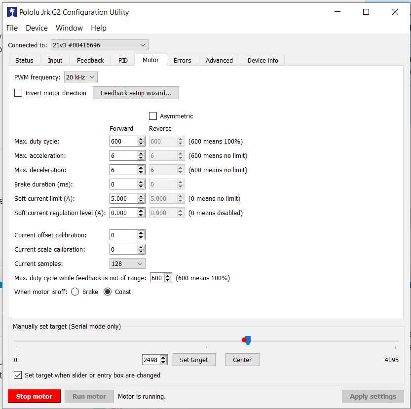
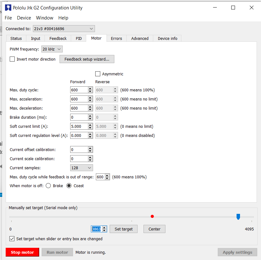
We generally recommend a motor controller that can handle continuous currents above the stall current of your motor (in this case 5.5A at 12V), so by that criterion the Jrk G2 21v3 would be underpowered. However, it doesn’t sound like your application would be loading the motor much, so with some precautions (e.g. acceleration limiting and the Jrk G2 21v3’s software current limiting), it would probably be fine.
As I mentioned before, the Jrk will need some kind of signal to tell it what the target speed is. For accuracy, I would recommend the USB, I2C, or TTL serial interfaces, so in that case you will probably want to connect your switch to a separate microcontroller (such as an Arduino or one of our Arduino-compatible A-Star controllers) and update the Jrk’s target speed whenever based on it’s position. Alternatively, you might be able to use the Jrk in analog speed control mode and connect your switch to the Jrk with some additional, carefully selected, circuitry to provide the right voltage for your desired speeds.
Thank you Brandon for all the help. I’ll get a motor and controller on order. I have an Arduino Uno I will try to interface with a switch and Jrk. I’m just starting my journey of learning on all this micro-controller stuff so all most all this is unfamiliar. Thanks again.
Hi Brandon
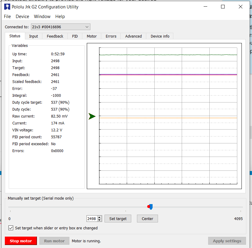
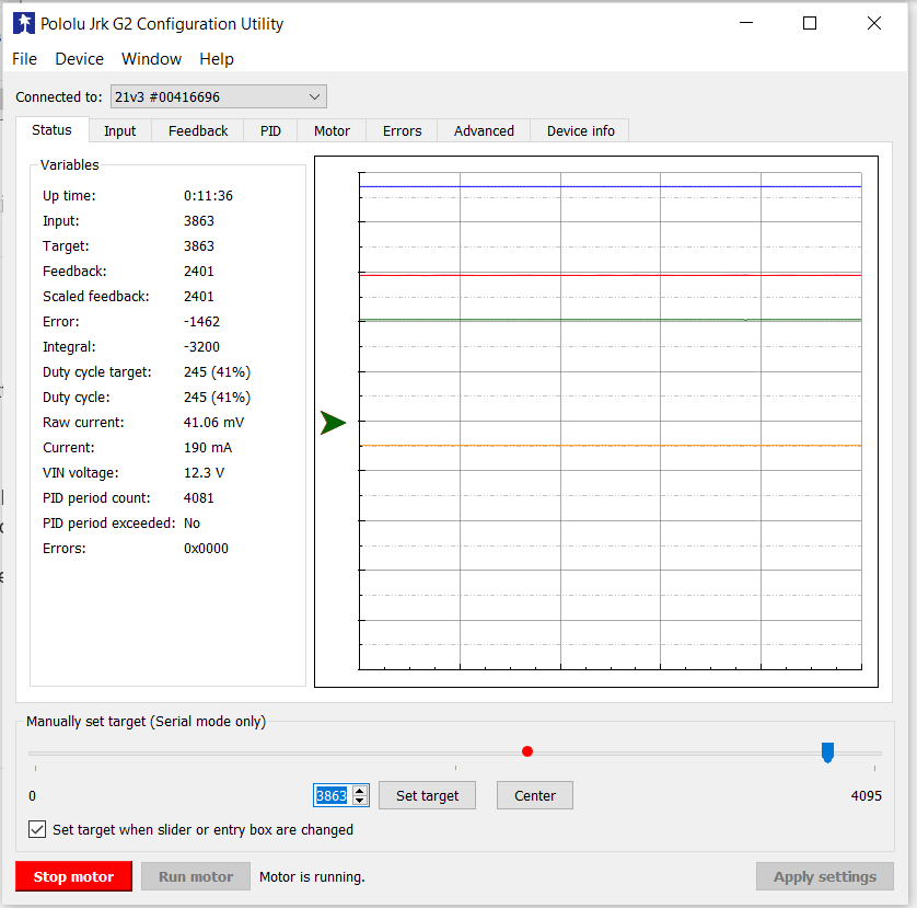
I got the gearmotor (19:1) and controller (21v3) working. I’m having trouble turning feedback and getting the target speed. This is as close as I can get, but if I change the speed its unstable. Here are some screen shots. I’ve been trying to follow the user guide you sent. Is there maybe a video on this. Thanks for your help.
Thanks Brandon. Still not getting up to speed with large error. I"m trying to set the motor speed to 500 RPM. Now that the full scale has changed to 4095 I calculated that 500 rpm would be 3863? Any way here are my settings. I must have something different than your setup. I am using a 12V, 10A power supply. Thanks for helping me and spending your time.
Could you post a copy of your Jrk G2 settings file so I can load it onto the Jrk in my setup and see if I get the same behavior? You can save a copy of your settings file from the “File” drop-down menu of the Jrk G2 Control Center while your controller is connected (it saves as a simple .txt file).
Also, could you describe the behavior you’re seeing in more detail? For example, does it match the target speed better at lower speeds or is it always slower than you’re commanding?
Heres the file. I did discover the following target speed? / error
2500 / ~0
2800 / ~0
2900 / ~10
3000 / ~30
3500 / ~520
But 3000 and 3500 are past the Duty Cycle of 600, thus the motor can’t spin any faster. So one thing is I don’t understand Duty Cycle (600) vs Target (4095) and how these relate to the RPM of the motor. The motor max RPM is 540 and Im wanting to operate at 350 - 500 RPM so how do I convert Duty Cycle / Target values to motor RPM. This is progress, thanks Brandon
Where P is the number of rising edges that were measured on the FBT pin in the last PID period (10ms by default, which is the case here). When you set a target, the Jrk is trying to make the scaled feedback (which is the same as the feedback in this case) match the target with as little error as possible. As you mentioned, the range of possible targets is higher than what your motor can actually reach, so the error you’re seeing at the higher target values is expected.
Please note that since the Jrk is only counting rising edges of a single encoder channel, it is receiving 16 counts per revolution (CPR) of the motor shaft. The RPM that you mentioned is at the output shat, which means you need to account for the gear ratio (18.75:1) to correlate it to the encoder output. Ultimately, to calculate what target value to send to get a specific RPM at the output shaft (which I’m calling x in the formula below), you can use the following equation:
So, with your settings, if you want a maximum speed of 500 RPM in either direction, your target values should be between 1248 and 2848. Similarly, to get a speed of 350 RPM in one direction your target would be 1488 and in the other direction it would be 2608.
Hi Brandon. This is great and the details I needed. The motor seems to be running at the Target RPM with minimum error and adjusts to maintain speed when I apply torque resistance. These formulas were key, thank you.
Is there a resource for converting to use an Arduino Uno board instead of the Configuration Utility? Like a guide, instructions, video?
For switching to Arduino, I recommend using our Jrk G2 library for Arduino, which should help make the communication easier. You can find some connection information depending on the interface you choose (I2C or TTL serial) in the library’s README page. Additionally, the example programs have some details about how the Jrk should be configured.
If you have trouble getting it to work, you can post details about what you’ve tried, and I would be happy to help further. Probably the most helpful information you can post is pictures of your setup that show all of your connections, as well as an updated settings file.