Hello everyone,
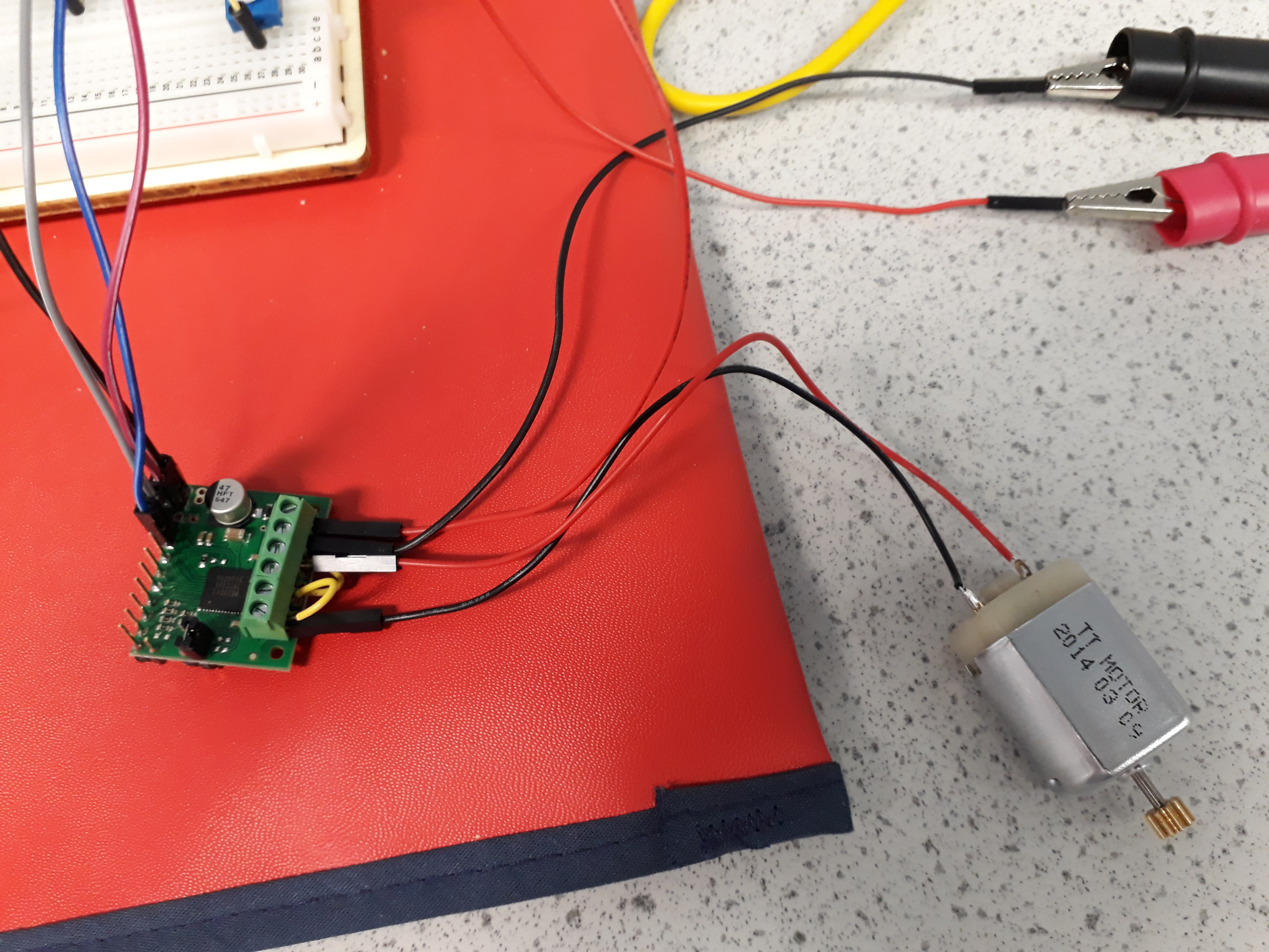
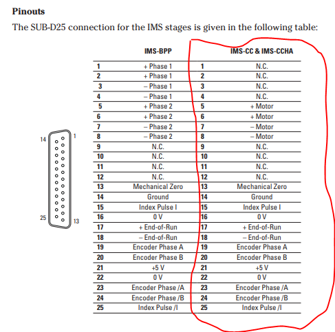
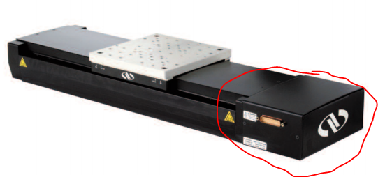
My project is to realize a motor DC driver for a Long-Travel Linear Stages. The connection with the motor is made using a DB25 port(please check the images).
I would like some advice on how to control this type of dc motor with which type of driver…
thanks in advance.
Hello.
We are not familiar with that device and cannot tell you exactly how all of the pins work. It is possible that the motor is a brushed DC motor. If so, the outputs of our brushed DC motor drivers or controllers could probably be connected to the +Motor and -Motor pins to make the motor move. The rest of the pins appear to be for sensors (like encoders and limit switches) integrated into the device to determine the position of the stage. Generally, sensors like that need a power supply, which could be what the +5V and Ground pins are for.
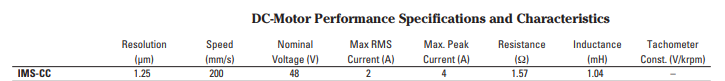
We do not have an out of the box solution that would work with all of logic signals that connector appears to provide. Our RoboClaw motor controllers can use feedback from a quadrature encoder to control the position of a brushed DC motor, but you might still need to use something like a microcontroller to monitor the state of any limit switch outputs and control the RoboClaw appropriately. Alternatively, you could use a microcontroller with your own custom firmware to monitor all of the appropriate sensor pins and one of our brushed dc motor drivers to provide variable power to the motor. Our TB67H420FTG Dual/Single Motor Driver Carrier board should work well with the voltage and current indicated in the picture you posted.
-Nathan
Thank you very much for your help I intend to leave on the second solution with TB67H420FTG Dual/Single Motor Driver Carrier.
what did you mean by “could use a microcontroller with your own custom firmware to monitor all of the appropriate sensor pins” that is to say for example I can control the position of a brushed DC motor with code ARDUINO ?
Thanks again.
Yes, it seems like an Arduino could probably be programmed to do that. The motor driver I mentioned will work with an Arduino board that uses a logic voltage between 3 an 5V (which should be most of them).
-Nathan
Okay, I just ordered it. I just have one question: do you know why the DC motor has 4 pins? (two + Motor and two -Motor).
N.P
The connectors on a DB25 port are small, so it is possible they are internally connected to one another and there are two so each has to handle less current. You could use a multimeter to check the resistance between the pins (which should be close to zero) or between each of the motor+ and motor - pins to see if it matches the 1.57ohm specification in the table.
-Nathan
Thank you for your answer.
while waiting to receive my board I’m doing some research on how to manage the encoder. I have 6 pins to encode it. Can I use only the 2 pins : A and B as on this code to realize the controller ? 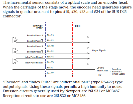
That seems like it should be possible. You might use an oscilloscope to measure the voltage of the Phase A and B pins relative to ground as the encoder turns to see if it oscillates between +5V and GND,
-Nathan
Hi Nathan,
I am currently testing my card but I have a problem. I have a feeling it’s not working. Because there’s no movement of the engine
Attach some picture of my set up and code arduino.
Can you help me please.
Thank you sketch_jul20a.ino (787 Bytes)
Hello.
It looks like you do not have the PWMA pin connected to anything. By default that pin is pulled low and the driver will not provide power to the motor in that state. It looks like your code is OK; as the truth tables on the product page show, pulling INA1 high, INA2 low, and sending PWMA a PWM signal should cause the motor to operate in a forward/brake low cycle. If you check all of your connections and still have problems, you might try pulling the appropriate pins high by connecting them to the VCC (5V out) pin on the driver to see if the motor moves.
-Nathan