
I am building an pid controller for 227:1 Metal Gearmotor 25Dx56L mm MP 12V with 48 CPR Encoderusing MC33926 Motor Driver Carrier. I am having trouble sending the signals for the pwm1, pwm2, in1, in2, slew, en, fb. I know the board is getting voltage and I know the motor work but I am not sure if the driver and my controller are talking or if they are passing information in the right format. Please help me with any advice you an offer.
I am sorry you are having trouble getting your MC33926 motor driver to work. Can you tell me more about your setup? What are you using to send your signals to the motor driver? How are you supplying power? Can you also post pictures that clearly show your connections and soldering joints?
-Jon
Thanks for the quick response
I am using ALTERA DE2-115 BOARD. Here is the info the connector I’m using
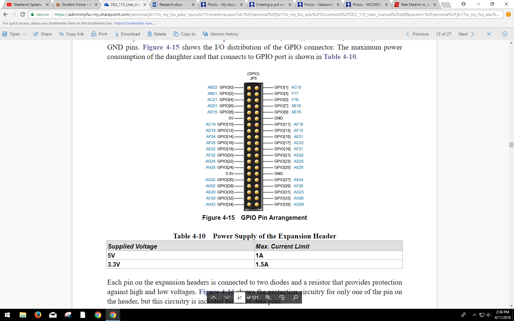
Here are my connections:
|OUT2| TO MOTOR+
|OUT1| TO MOTOR-
|VDD| TO ALTERA BOARD GPIO 5V
AGND TO ALTERA BOARD GND
|IN2| TO ALTERA BOARD GPIO
|IN1| TO ALTERA BOARD GPIO
|PWM/D2| TO ALTERA BOARD GPIO
|PWM/D1| TO ALTERA BOARD GPIO
|FB| TO ALTERA BOARD GPIO
|EN TO ALTERA BOARD GPIO
|SLEW| TO ALTERA BOARD GPIO
|INV| TO ALTERA BOARD GPIO
VIN TO POWER SUPPLY 12V
PGND TO POWER SUPPLY 12V
MOTOR ENCODER A TO ALTERA BOARD GPIO
MOTOR ENCODER B TO ALTERA BOARD GPIO
MOTOR ENCODER GND TO GND
ALL GROUNDS ARE CONNECTED TO A COMMON GROUND ON THE FRAME
I recommend simplifying your setup so we can focus on getting the motor driver to control your motor with minimal control signals. In particular, you should remove the feedback part of your system and replace all GPIO-based logic signal connections with a connection to either 5V or GND on your Altera. If you are not sure whether to connect a pin to logic high (5V) or logic low (GND), I recommend reading through the Pinout and Basic Application Connections sections of the MC33926 Motor Driver Carrier’s product page.
If you cannot get the motor to run after testing it in that kind of setup, can you post pictures that show your connections and soldered joints?
By the way, you mention connecting “PGND” to 12V. I am not entirely sure which pin you are referring to, but just in case, the larger GND pad on the MC33926 board should connect to GND on your 12V supply (not the 12V positive power side).
-Jon
Thanks for the quick response Jonathan!
Sorry for the typo. I did connect the big GND to the power supply GND. When you say
you should remove the feedback part of your system and replace all GPIO-based logic signal connections with a connection to either 5V or GND on your Altera
You mean I need to put all the signals that I want hi to the 5V on the Altera and to GND for all the signals that I want low, correct?
Yes, that is correct.
-Jon
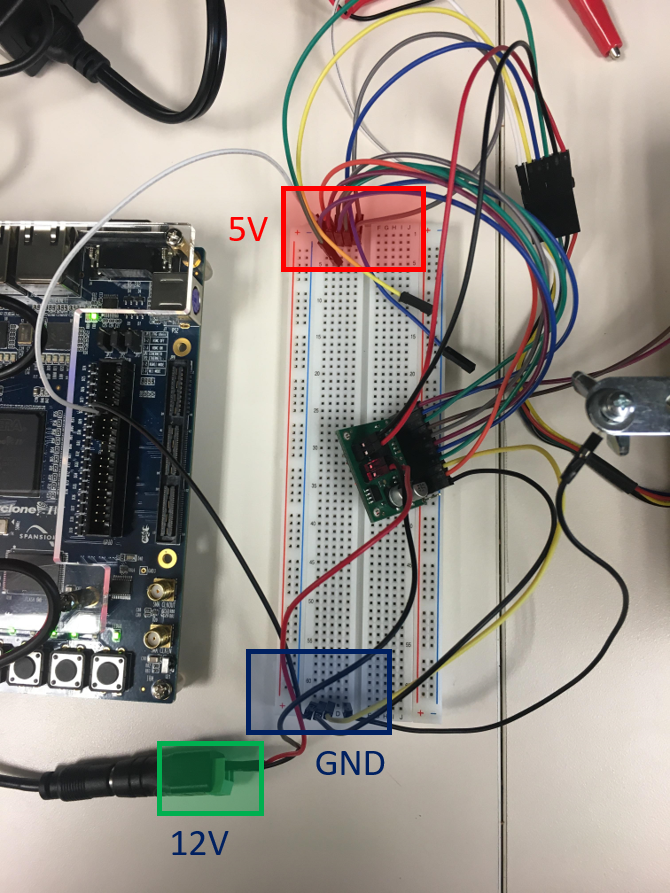
Jon, I tried your suggestion. The driver does NOT get 12V. I get 12V out of the power supply and through the wires connecting to the driver but the driver does not get 12V. I have The driver gets the 5V from the Altera board.
Below is a picture of the testing setup.
.
It is not entirely clear what you mean when you say “The driver does NOT get 12V.” Do you mean that the motor driver is not producing 12V across its outputs? If that is not the case, can you explain what you mean? Can you post close-up pictures that show the soldering joints on the underside of your board? Also, it is difficult to follow your connections from the picture you posted. Can you tell me which pins you are setting high and low (or leaving disconnected)?
-Jon
Thanks for your continuous help Jon!
Here are new pictures. The picture on the left is connected to a 5V power supply to simulate the signal from the Altera board. The signals connected to 5V are VDD, IN2, PWM2, SF, INV and the ones to ground are IN1, PWM1, GND.
The one on the right is connected to a 12V power supply and motor. Two power supply wires are connected to the board and the two wires to the motor are connected there. Both sides of the bread board have a connection to a common ground.
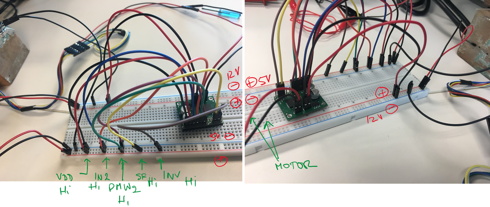
When I measure voltage on the wire coming from the power supply before connecting it to the board I measure 12V when I connected to the board I get no voltage. I don’t see the same thing on the other side with the 5V. I measure 5V before connecting the VDD to the board and after I connected to the board
It looks like the connections on your boards are not soldered. Soldering is necessary for making a good electrical connection, and the lack of a good electrical connection is likely the reason you are not able to supply power to your motor drivers. I recommend soldering your joints, and if you are new to soldering, I also recommend reading through Adafruit’s soldering guide. In particular this part, which shows what an ideal joint looks like, should be useful.
-Jon
Thanks for the advice. I got the motor running and the driver works well.
My next challenges are
- Sorting out the signals to the board. I looked at the datasheet for freescale H-bridge and all signals are logical inputs/outputs except for the feedback signal. Does this sound right to you?
- PWM implementation. Also, for the PWM part, I feel need to cycle IN1 between the forward and free wheel low states from table 6 in the freescale datasheet. Does this sound right to you?
Thanks,
JS
I am glad that you got your driver to work and that it is working well!
- That sounds right; FB is an analog output.
- Switching IN1 high and low (and keeping all other inputs the same) will alternate between driving in the forward direction and braking low. Whether or not that is right for you depends on your system and whatever you want your PID controller to do.
-Jon
Thanks Jon! Regarding the PWM, have you seen how other folks implement it? Do you have any suggestions?
Switching IN1 off and on to alternate between driving in the forward direction and braking low would be controlling the motor in drive-brake operation, which is what we prefer to do for our motor drivers as it produces a more linear relationship between duty cycle and motor speed. The alternative, drive-coast operation, can be achieved by sending a PWM signal to the PWM/!D2 pin, which disables the outputs during the off cycles (i.e. the motor coasts instead of brakes). I expect the drive-brake operation you have planned to be reasonable for PID control.
-Jon
Jon,
I am using the code below for my pwm and it does not change the setpoint (the motor rotates at the same speed and in the same direction regardless of the input).
I must be doing something wrong. Please let me know your suggestions on how to modify this code to make it work properly.
--------------------------------------------------------------------------------
--
--   FileName:         pwm.vhd
--   Dependencies:     none
--   Design Software:  Quartus II 64-bit Version 12.1 Build 177 SJ Full Version
--
--   HDL CODE IS PROVIDED "AS IS."  DIGI-KEY EXPRESSLY DISCLAIMS ANY
--   WARRANTY OF ANY KIND, WHETHER EXPRESS OR IMPLIED, INCLUDING BUT NOT
--   LIMITED TO, THE IMPLIED WARRANTIES OF MERCHANTABILITY, FITNESS FOR A
--   PARTICULAR PURPOSE, OR NON-INFRINGEMENT. IN NO EVENT SHALL DIGI-KEY
--   BE LIABLE FOR ANY INCIDENTAL, SPECIAL, INDIRECT OR CONSEQUENTIAL
--   DAMAGES, LOST PROFITS OR LOST DATA, HARM TO YOUR EQUIPMENT, COST OF
--   PROCUREMENT OF SUBSTITUTE GOODS, TECHNOLOGY OR SERVICES, ANY CLAIMS
--   BY THIRD PARTIES (INCLUDING BUT NOT LIMITED TO ANY DEFENSE THEREOF),
--   ANY CLAIMS FOR INDEMNITY OR CONTRIBUTION, OR OTHER SIMILAR COSTS.
--
--   Version History
--   Version 1.0 8/1/2013 Scott Larson
--     Initial Public Release
--   Version 2.0 1/9/2015 Scott Larson
--     Transistion between duty cycles always starts at center of pulse to avoid
--     anomalies in pulse shapes
--
--------------------------------------------------------------------------------

LIBRARY ieee;
USE ieee.std_logic_1164.all;
USE ieee.std_logic_unsigned.all;

ENTITY pwm IS
  GENERIC(
      sys_clk         : INTEGER := 50_000_000; --system clock frequency in Hz
      pwm_freq        : INTEGER := 100_000;    --PWM switching frequency in Hz
      bits_resolution : INTEGER := 8;          --bits of resolution setting the duty cycle
      phases          : INTEGER := 1);         --number of output pwms and phases
  PORT(
      clk       : IN  STD_LOGIC;                                    --system clock
      reset_n   : IN  STD_LOGIC;                                    --asynchronous reset
      ena       : IN  STD_LOGIC;                                    --latches in new duty cycle
      **duty      : IN  STD_LOGIC_VECTOR(bits_resolution-1 DOWNTO 0); --duty cycle**
      pwm_out   : OUT STD_LOGIC_VECTOR(phases-1 DOWNTO 0);          --pwm outputs
      pwm_n_out : OUT STD_LOGIC_VECTOR(phases-1 DOWNTO 0));         --pwm inverse outputs
END pwm;

ARCHITECTURE logic OF pwm IS
  CONSTANT  period     :  INTEGER := sys_clk/pwm_freq;                      --number of clocks in one pwm period
  TYPE counters IS ARRAY (0 TO phases-1) OF INTEGER RANGE 0 TO period - 1;  --data type for array of period counters
  SIGNAL  count        :  counters := (OTHERS => 0);                        --array of period counters
  SIGNAL   half_duty_new  :  INTEGER RANGE 0 TO period/2 := 0;              --number of clocks in 1/2 duty cycle
  TYPE half_duties IS ARRAY (0 TO phases-1) OF INTEGER RANGE 0 TO period/2; --data type for array of half duty values
  SIGNAL  half_duty    :  half_duties := (OTHERS => 0);                     --array of half duty values (for each phase)
BEGIN
  PROCESS(clk, reset_n)
  BEGIN
    IF(reset_n = '0') THEN                                                 --asynchronous reset
      count <= (OTHERS => 0);                                                --clear counter
      pwm_out <= (OTHERS => '0');                                            --clear pwm outputs
      pwm_n_out <= (OTHERS => '0');                                          --clear pwm inverse outputs
    ELSIF(clk'EVENT AND clk = '1') THEN                                      --rising system clock edge
      IF(ena = '1') THEN                                                   --latch in new duty cycle
        half_duty_new <= conv_integer(duty)*period/(2**bits_resolution)/2;   --determine clocks in 1/2 duty cycle
      END IF;
      FOR i IN 0 to phases-1 LOOP                                            --create a counter for each phase
        IF(count(0) = period - 1 - i*period/phases) THEN                       --end of period reached
          count(i) <= 0;                                                         --reset counter
          half_duty(i) <= half_duty_new;                                         --set most recent duty cycle value
        ELSE                                                                   --end of period not reached
          count(i) <= count(i) + 1;                                              --increment counter
        END IF;
      END LOOP;
      FOR i IN 0 to phases-1 LOOP                                            --control outputs for each phase
        IF(count(i) = half_duty(i)) THEN                                       --phase's falling edge reached
          pwm_out(i) <= '0';                                                     --deassert the pwm output
          pwm_n_out(i) <= '1';                                                   --assert the pwm inverse output
        ELSIF(count(i) = period - half_duty(i)) THEN                           --phase's rising edge reached
          pwm_out(i) <= '1';                                                     --assert the pwm output
          pwm_n_out(i) <= '0';                                                   --deassert the pwm inverse output
        END IF;
      END LOOP;
    END IF;
  END PROCESS;
END logic;
We do not make or carry that Altera board, so it is beyond the scope of our technical support to help you program it, but to start troubleshooting I recommend simplifying your code as much as possible (e.g. a set loop that only brings one pin high and low with fixed delays).
-Jon