Balboa appears to be an extremely well engineered robot – nice job, folks!
However, a few tests, shown below, reveal that the magnetometer is subject to severe hard iron distortion, perhaps due to the vicinity of the battery casings (I’m using alkaline AAs in my early tests and haven’t tried any others yet). Fortunately, this situation can be fixed.
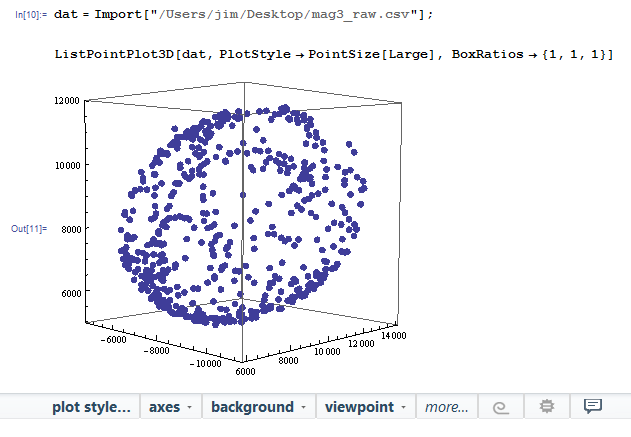
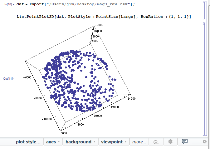
The basic test is simple: just hold the robot in the air and wave it around, covering as many 3D points as possible, while outputting the raw magnetometer readings over the serial port. Ideally, the magnetometer readings should map to the surface of a sphere centered on the origin. Here is what I got, showing a pronounced ellipsoid remarkably far from being centered on the origin (two different viewpoints shown):

The fact that the data DO map to a nice ellipsoid is very promising, though!
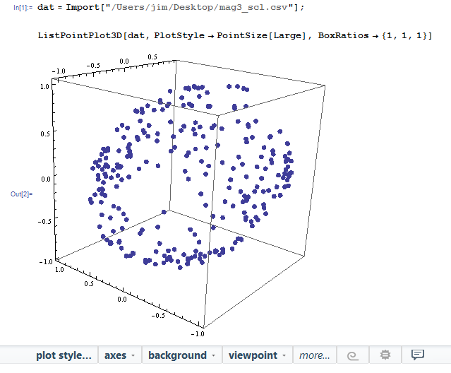
Most people try to correct magnetometer readings by finding a set of offsets and scale factors, using a simple axial min/max approach. But in this case, the major axis of the ellipsoid is pointing from one corner of the box diagonally to the other, which is impossible to correct by this method. I tried, though, using the Arduino program Calibrate2, attached in a zip file. The result is shown below, showing that the ellipsoid is now centered and less oblong, but these data would be useless to make a compass.
Linear algebra to the rescue! I used the approach described in this excellent blog article:
Sailboat Instruments: Improved magnetometer calibration (Part 1)
The author describes magneto, a fair sized C program that runs on a PC or a Mac (I use the Code::Blocks IDE on Win7). For convenience, I’ve collected all of the basic parts of magneto, described in the sailboatinstruments link, into one file that can be compiled and run on a desktop. See attached zip file.
This approach fits an ellipsoid to the data, avoiding statistical problems associated with the min/max approach, rotates the ellipsoid to align with the coordinate axes, scales the axial dimensions to a sphere, and rotates back. The result is a set of offsets and a nine element matrix correction that must be applied to the raw data.
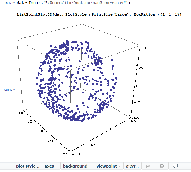
The magneto program output for the data set plotted above is as follows, and includes data initialization statements that can be incorporated into your code:
mag3_output.txt (693 Bytes)
The corrected data are as close to a perfect sphere as you can expect!
With these corrected data, it is possible to create a compass program with basic accuracy +/- 2 degrees or so, which is fine for navigating the Balboa around the room – providing that no metal objects are nearby to distort the compass readings. Who knows, though, that might increase the fun!
I’ve attached an Arduino program LIS3DLM_compass that demonstrates how to do the correction and make a compass, assuming that the Balboa is horizontally oriented.
To use these programs to calibrate your magnetometer, first use the Arduino IDE to upload the program Calibrate2 to Balboa. Instead of using the Arduino serial monitor to visualize the program output, use a terminal program like TeraTerm, capable of creating a log file, and use .csv as the file extension. Turn the robot about in 3D until the raw data collection process terminates with some scale and offset factors. Close and edit the resulting .csv file so that only the raw magnetometer data are included. Then, compile, link and run magneto as an interactive console program, entering the above .csv filename as input. I suggest to enter 1000 for Hm. Magneto publishes correction data which can then be incorporated into the source code for another program, like the included LIS3MDL_compass.
When I get around to it, I’ll post a program showing the Balboa driving a course defined by a set of magnetometer headings, and also, a tilt compensated compass that makes use of the accelerometer.
By the way: there is another, very sophisticated method of mapping magnetometer or other data to the unit sphere which will run on any Arduino: Gauss-Newton mapping. It works much better than the min/max axial method, and the linked implementation also yields 6 independent parameters. However, to correct for a tilted ellipsoid as encountered here requires the 9 independent parameters returned by magneto. In any case, this is a one-off job and there is no reason to burden the Arduino with such a task.
Happy to entertain questions or comments!
balboa_mag.zip (127.4 KB)


