Controlling Motor (Product 4801) Using Encoder+Dual Motor Driver Shield (Product 2520) and PID from Encoder

Hello, I am trying to develop a control system for my motor ( Pololu - 4.4:1 Metal Gearmotor 25Dx63L mm HP 6V with 48 CPR Encoder ). My interface to driving the motor is the Dual TB9051FTG Motor Driver Shield for Arduino. In that library there is a function setSpeed for both motors, that controls a pulse width modulated output and a logical direction I/O.
(correct me if I am wrong).

My hope was to use a PID controller that used the encoder interrupts to track the rotor angle to the nearest (2PI/48) radians and some assumed theta naught then use that library function to control the power applied to the rotor (which should manifest itself as some omega given a particular load.)

I am running into two main problems.

  1. Fluctuating Motion Deadzone:
    a. So, ideally, a setSpeed of 0 would result in no motion, 1 would result in super slow motion and 400 would result in very fast forward motion. This is not the case. There is a deadzone from (based on some experiments in my system) about -155 to 155 where setting motor speed to anything in that range results in no motion. This makes it so my controller needs to be adjusted to some range to account for the deadzone. If my controller gives a value of 0.1, then it is not to set the motor speed to 40, but rather somewhere in between the no-motion zero value and 400.
    b. This value of no-motion zero is not constant. Based on what is going on with the other motor and the load, this value has the potential to change during runtime and needs to be accounted for in the algorithm. The fluctuating nature of this fundamental value is difficult to manage and adjust for as the system runs.

  2. Motion is Jumpy/Not Easily Mapped to Analog Space (especially at theoretically low speeds)
    Problem two is essentially that if you go JUST above the zero mentioned in part 1, you move way too fast. My control system works to a certain extent, but it suffers from the fact that any motion that it introduces overshoots the desired theta, then it needs to readjust and during that readjustment, overshoots the desired theta in the opposite direction, leading to an oscillating steady state. I see this as a fundamental problem with the equipment rather than the algorithm. The speed setting does not perform as a spectral function just above the zero power. IE, you are either rotating at 0 rad/s at setSpeed=155 (current theoretical 0) or you are rotating at like 8*(2PI) rad/s (8 rev/s) if you set 156. You cannot set something between 155 and 156, so you run into trouble.

With all this in mind, do you have any advice. I am a motor and robotics novice to say the most, so perhaps I am missing huge chunks of knowledge of motor theory that abstract my control system to an inappropriate extent that doesn’t account for the physics of the true system. Any suggestions on how I could sure up my model/control system?

Hello.

The behavior you are observing does not sound unusual. Most motors require a noticeably higher voltage and draw more current to get started since they need to overcome their own internal static friction and cogging torque, and the 6V high-power (HP) 25D gearmotors have particularly strong magnets for their size that generate significant cogging torque. Usually, after you overcome the starting torque, you should be able to slow the motor down to slower speeds, and you implementing closed loop control with encoder feedback should allow you to extend that range, but there will still be some minimum speed where motor’s the cogging torques make it difficult to operate it. It is not exactly clear what type of speed/position control resolution you are trying to achieve, but I suspect you have reached or are approaching that limit.

If your application requires very low speed operation, then one option might be to use a lower power motor, like one of our 6V low-power (LP) 25D gearmotors (which uses less powerful magnets and therefore has a lower cogging torque, though we have not characterized that in detail). Using a gearmotor with a higher gear ratio can also make it easier to run at low speeds, but both of those options will come at the cost of reducing your maximum achievable speed. You might also consider whether a stepper motor might be more appropriate in your application.

- Patrick

This will lead back to my original question.

I was concerned in part about tracking direction of angular velocity of the rotor. I was reading the document about the encoder which says

The frequency of the transitions tells you the speed of the motor, and the order of the transitions tells you the direction.

So I started trying to differentiate interrupt types so I could get the direction of the motor (so if the motor is direction reversed under load I know it has moved in the last direction). In my investigation, I found that my program is only recognizing falling edge interrupts (unless it is only looking for rising edge ones).

test_interrupts.ino (1.8 KB)

This is the console output I am getting.

rising_cnt_0: 0
falling_cnt_0: 476
rising_cnt_1: 0
falling_cnt_1: 476

If I comment out lines 29 and 31 so I only look at rising edge interrupts and rerun, I get this.

rising_cnt_0: 485
falling_cnt_0: 0
rising_cnt_1: 486
falling_cnt_1: 0

I could think of some reasons for this

  1. Electrically not connected correctly - this should not be the case since it is picking up falling edge interrupts

  2. You cannot have RISING and FALLING edge on same interrupt pin. I looked on the Arduino site and it seems you should be able to use one interrupt pin, recognizing RISING and FALLING edge.

  3. This leaves me to believe that the Arduino simply cannot keep up with the incoming interrupts from the encoder. This would make feedback control of the sort I am trying to do almost impossible.

Has Polou done any sort of testing with 4801+encoder and the Arduino+shield? Do you have any reason to believe the Arduino can keep up with the frequency of the interrupts coming from the motor?

Maybe I was wrong about concern 2

If I run with this in the setup

  attachInterrupt(digitalPinToInterrupt(LM_INT0_PIN), update_lm_theta0_r, RISING);
  attachInterrupt(digitalPinToInterrupt(LM_INT0_PIN), update_lm_theta0_f, FALLING);
  attachInterrupt(digitalPinToInterrupt(LM_INT1_PIN), update_lm_theta1_r, RISING);
  attachInterrupt(digitalPinToInterrupt(LM_INT1_PIN), update_lm_theta1_f, FALLING);

//  attachInterrupt(digitalPinToInterrupt(LM_INT0_PIN), update_lm_theta0_f, FALLING);
//  attachInterrupt(digitalPinToInterrupt(LM_INT0_PIN), update_lm_theta0_r, RISING);
//  attachInterrupt(digitalPinToInterrupt(LM_INT1_PIN), update_lm_theta1_f, FALLING);
//  attachInterrupt(digitalPinToInterrupt(LM_INT1_PIN), update_lm_theta1_r, RISING);

I get

rising_cnt_0: 0
falling_cnt_0: 486
rising_cnt_1: 0
falling_cnt_1: 486

But if I run with

//  attachInterrupt(digitalPinToInterrupt(LM_INT0_PIN), update_lm_theta0_r, RISING);
//  attachInterrupt(digitalPinToInterrupt(LM_INT0_PIN), update_lm_theta0_f, FALLING);
//  attachInterrupt(digitalPinToInterrupt(LM_INT1_PIN), update_lm_theta1_r, RISING);
//  attachInterrupt(digitalPinToInterrupt(LM_INT1_PIN), update_lm_theta1_f, FALLING);

  attachInterrupt(digitalPinToInterrupt(LM_INT0_PIN), update_lm_theta0_f, FALLING);
  attachInterrupt(digitalPinToInterrupt(LM_INT0_PIN), update_lm_theta0_r, RISING);
  attachInterrupt(digitalPinToInterrupt(LM_INT1_PIN), update_lm_theta1_f, FALLING);
  attachInterrupt(digitalPinToInterrupt(LM_INT1_PIN), update_lm_theta1_r, RISING);

I get

rising_cnt_0: 484
falling_cnt_0: 0
rising_cnt_1: 484
falling_cnt_1: 0

Would anyone happen to know if you can have rising and falling edge interrupts on the same pin?

You cannot attach multiple interrupts to a single external interrupt pin, but you can reconfigure your interrupt to trigger whenever the pin changes instead of triggering just on rising edges or just on falling changes. Here is an example of how you might do that :

attachInterrupt(digitalPinToInterrupt(encA), update_countA, CHANGE);

This will help you maximize your encoder resolution, but it also increases the potential of missing counts since your interrupt service routine will probably be more complicated and take longer than before.

- Patrick

If the order of the rising and falling edge on both sensors matters, how can I determine direction other than by checking what speed I set? What if there is back-force that makes it rotate in the opposite direction while speed is 0? Is there a way to check inside if it was rising or falling edge?

Yes, you can determine direction with just a quadrature encoder without looking at the speed command you are sending the motor. Whenever one encoder output rises or falls, you can to look at the state of the other output to determine direction.

You might check out this video which gives a nice description of how quadrature encoders work. It gets into details about how you can determine direction around three-and-a-half minutes into the video.

- Patrick

I’m concerned reading the digital pin in my interrupt and trying to process/record data for outside-of-isr processing isn’t going to work. Tried that encoder library. Didn’t work too well. Is it possible to fan out pins from the encoder to two Arduino inputs and setting one up to trigger on rise and the other on fall so I don’t have to digital read to get state? Is there a better way to do this?

Is there a best algorithm for tracking direction outside of IRQs?

My algorithm is to write a number (0-3 depending on the interrupt+digital read state) into a 4-element array and iterate index-to-write, then outside of interrupt, read that array to determine direction. I am getting sequences of numbers 0-3 in that array that I don’t expect based on what I am seeing in a simple paired-down program. I think my IRQs are being skipped due to processing in other IRQs and my program is not able to determine direction from what is in the array.

This is the subsection of the code that is the algorithm I described.

  if(idx_left == 0)
  {
    last_idx_filled = 3;
  }
  else
  {
    last_idx_filled = idx_left-1;
  }
  
  if(left_irqs > 0)
  {
    switch(last4_left[last_idx_filled]) 
    {
      case 0:
        if(last4_left[last_idx_filled] == 3)
        {
          pos_left = pos_left+left_irqs+queued_unknown_irqs_left;
          queued_unknown_irqs_left = 0;
          ldir_frwrd++;
        }
        if(last4_left[last_idx_filled] == 1)
        {
          pos_left = pos_left-left_irqs-queued_unknown_irqs_left;  
          queued_unknown_irqs_left = 0;
          ldir_bkwrd++;       
        }
        else
        {
          queued_unknown_irqs_left=queued_unknown_irqs_left+left_irqs;
          ldir_unkwn++;
        }
        break;
      case 1:
        if(last4_left[last_idx_filled] == 0)
        {
          pos_left = pos_left+left_irqs+queued_unknown_irqs_left;
          queued_unknown_irqs_left = 0;
          ldir_frwrd++;
        }
        if(last4_left[last_idx_filled] == 2)
        {
          pos_left = pos_left-left_irqs-queued_unknown_irqs_left;  
          queued_unknown_irqs_left = 0; 
          ldir_bkwrd++; 
        }
        else
        {
          queued_unknown_irqs_left=queued_unknown_irqs_left+left_irqs;
          ldir_unkwn++;
        }
        break;
      case 2:
        if(last4_left[last_idx_filled] == 1)
        {
          pos_left = pos_left+left_irqs+queued_unknown_irqs_left;
          queued_unknown_irqs_left = 0;
          ldir_frwrd++;
        }
        if(last4_left[last_idx_filled] == 3)
        {
          pos_left = pos_left-left_irqs-queued_unknown_irqs_left;  
          queued_unknown_irqs_left = 0;  
          ldir_bkwrd++;
        }
        else
        {
          queued_unknown_irqs_left=queued_unknown_irqs_left+left_irqs;
          ldir_unkwn++;          
        }
        break;     
      case 3:
        if(last4_left[last_idx_filled] == 2)
        {
          pos_left = pos_left+left_irqs+queued_unknown_irqs_left;
          queued_unknown_irqs_left = 0;
          ldir_frwrd++;
        }
        if(last4_left[last_idx_filled] == 0)
        {
          pos_left = pos_left-left_irqs-queued_unknown_irqs_left;  
          queued_unknown_irqs_left = 0;
          ldir_bkwrd++;  
        }
        else
        {
          queued_unknown_irqs_left=queued_unknown_irqs_left+left_irqs;
          ldir_unkwn++;          
        }
        break;                
    }
  }

I am not following your approach for handling the encoders in the code you posted, but my general impression is that it seems unnecessarily complicated and I don’t expect it to work well. There is probably not some specific “best algorithm” for reading encoders since what is best will depend on each application. However, I think you should be able to find some library or tutorial that will be well suited for what you are trying to do without having to come up with your own algorithm from scratch. The “Reading Rotary Encoders” Arduino Playground page has links to several libraries and examples that you could try.

- Patrick

I will try the encoder library.
I had tried it before in conjunction with a software-based PWM that used a timer interrupt that was firing every 10ms, and things got bad when I tried to use the encoder.
I’m in a situation now where I have a software PWM that essentially turns on the hardware PWM for a subset of the time of the period (the software duty cycle) based on reading millis(). Using this software PWM, I am able to make the motor rotate more slowly.
Using millis is more of an as-possible service depending on the frequency with which millis is sampled. As such, I need to be able to have enough loops per second to activate and deactivate the motors in this software PWM.
I am hoping the ISR’s in this library aren’t too laggy, which was what I had experienced before when using it with the timer interrupt that powered the software PWM.

UPDATE
The encoder library seems to work okay. I still get this behavior where the motor seems to settle at what the controller sees as zero error then somehow it receives IRQs when the motor doesn’t seem to be moving that make it oscillate back and forth over the 0-error point. I guess my next question is whether you might have stepper motors that are the same form factor as this motor Pololu - 4.4:1 Metal Gearmotor 25Dx63L mm HP 6V with 48 CPR Encoder

I am glad to hear that it sounds like you are getting closer! Regarding the counts you are seeing when the motor is still, if you have not already, I would suggest testing your encoder reading algorithm by itself (separate from your motor driving and PID code) so you can be more confident about whether the encoder reading is really the problem. If it is, then you might be able to narrow down the possible causes by monitoring your encoder signal lines with an oscilloscope. If you see the signals on the wires changing when the motor is still, that might suggest there is some source of electrical interference. If you do not, then there is probably something going on with the interrupts in the background of your code.

We do not have any stepper motors that have the same form factor as our 25D brushed DC gearmotors, though we do have a few that are around the same size. Here is a link to our selection of stepper motors.

- Patrick

A couple of tests on that front.

  1. With my software PWM scheme I did a test where I feed the software PWM a non-zero value until 48 or greater is read on the encoder (should rotate a full loop), then I write 0. When I do this, I see about half a rotation. The final count is 136.
  2. I use the regular hardware PWM on the Arduino and keep writing a value of (I think) 170ish out of 400 based on the shield library until 48 counts are reached at which point I write zero. Result here is a full rotation but I end up reading 96 counts.

Maybe it’s really noisy on startup/slow down?

Have you established whether or not the encoder library you are using works correctly if you upload a program that only reads the encoder by rotating your gearmotor’s shaft manually. (You should not have to generate any PWM signals for that test.) If you rotate the gearbox output shaft 360°, then the program should report around 210 counts. (Factoring in the gear ratio of product #4801, the encoder provides 211.2 counts per revolution.)

- Patrick

I did not take into account the factor. That is throwing off a lot of my assumptions. I can perform that test. Just so I’m clear, there would be no power being injected to the motor? I would move the rotor by twisting it myself?

Correct. The objective of the test I am suggesting is to isolate your encoder reading algorithm and library from everything else as much as possible, so there should be no code other than the bare minimum you need to read the encoder and you would just rotate the motor by hand.

- Patrick

I ran two tests.

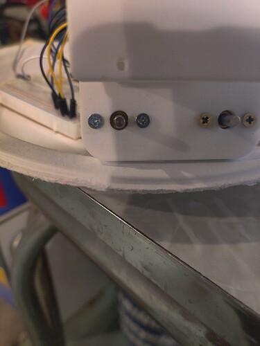
  1. Motors in enclosure. I do this because I think the screws going into the body of the motor may be a variable here. Motors screwed into an enclosure with arms attached to the rotor. This allows only limited range of motion. I show the enclosure below without the arms attached.

Rotating left motor counterclockwise to the max before hitting the right motor arm gave me a measurement of 80. Rotating it clockwise until it hit the enclosure gave me a measurement of -16.

Rotating the right motor clockwise until it hit the left motor arm gave me a measurement of -65 (which I would have expected to be -80 based on the other measurement and that the enclosure and arms are symmetrical). Rotating the right motor counterclockwise until it hit the enclosure gave me 15, which is close to the -16 in the test on the left motor.

Removing the motors from the enclosure and rotating them one revolution yielded 208 for the left motor and -208 for the right motor, since I rotated them in opposite directions.

I think I should rerun a lot of my testing now that I understand how the 4.4:1 ratio plays into the encoder. The encoder seems to be working in general. Might be worth a test to try to rotate the motors quickly at the same time to see if–what I assume is an interrupt based scheme in the library–can keep up.

As mentioned on the motor’s product page, we recommend screwing no further than 6 mm (0.24″) into the screw hole. As long as you are following that recommendation, the screws should not be a factor.

You proposal for how to proceed sounds okay. My best advice at this point is try to avoid adding too many things back into your project all at once since that will make it easier to identify problems as they come up.

- Patrick